
Service manual


Troubleshooting ESIEN05-04
3–28 Part 3 – Troubleshooting
3
1
3
4
5
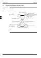
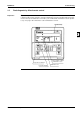
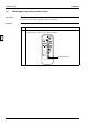
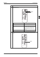
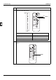
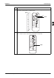
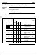
1.9 Troubleshooting by remote control Display / LED Display
Explanation for
Symbols
c : LED blinks / w : LED on / x : LED off / — : No connection with troubleshooting
: High probability of malfunction
{ : Possibility of malfunction
: Low probability of malfunction
— : No possibility of malfunction (do not replace)
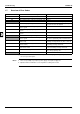
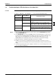
1.9.1 Indoor Malfunctions
Indoor
Unit Mal-
functions
Indoor Unit
LED Display
Note 2
remote
control
Display
Location of Malfunction Contents of Malfunction Details of
Malfunction
(Reference
Page)
H1P H2P Other
than PC
Board
PC Board
Out-
door
Unit
Indoor
Unit
remote
control
cc*Note 1 — — — — Normal → to outdoor unit —
cw A1 ——{ — Malfunction indoor unit PC
board (For troubleshoot-
ing by LED, refer to p.27.)
3–32
cx
w —
x —
cc A3 — — — Malfunction of drain water
level system
3–33
cc AF — — — Malfunction of drain sys-
tem
3–35
cc A6 — — Indoor unit fan motor lock 3–36
cc AJ — { — Malfunction of capacity
setting
3–38
cc C4 — — Malfunctioning heat
exchanger thermistor sys-
tem.
3–40
cc C5 — — Malfuncioning gaspipe
thermistor system.
3–40
cc C9 — — Malfunctioning suction air
thermistor system.
3–40
cc CC — — — — Malfunctioning of humidity
sensor system
3–43
cc CJ —— — Malfunctioning remote
control air thermisto
3–42