
Service manual


PCB Layout ESIEN05-04
1–120 Part 1 – System Outline
3
11
4
5
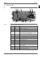
6.13 FAQ100B
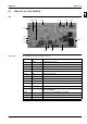
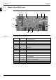
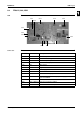
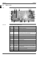
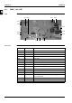
PCB The illustration below shows the PCB connectors.
Connectors The table below describes the PCB connectors.
X27A
X61A X60A
X19A
X11A
X98A X20A
X25A
X29A
X5A
X24A
X10A
X35A
X26A
X18A
X14A X15A
Connector Connected to Description
X5A X1M Terminal strip for P1/P2
X10A X2A on A2P Transformer PCB (secondary side)
X11A X1A on A2P Transformer PCB (primary side)
X14A S1Q Limit switch swing flap
X15A Connector float switch
X18A R2T Coil thermistor (liquid)
X19A R1T Air thermistor
X20A M1F Fan motor (power supply)
X24A X2A on A3P X24A is connected when the infrared remote control is used.
X25A M1P Drain pump motor
X26A M1F Fan motor( feedback signal)
X27A X2M Power supply & communication
X29A M1S Swing flap motor
X35A X1A on KRP4 Connector to group control adapter power supply (16 VDC) for
optional PCB KRP4
X60A X1A on DTA112 Connector for interface adapter
X61A X2A on DTA112 Connector for interface adapter
X98A C1 Capacitor for fan motor