
Service manual


ESIEN05-04 Switch Box Layout
Part 1 – System Outline 1–95
3
4
5
1
Part 1
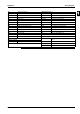
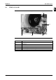
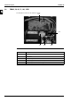
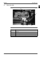
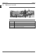
5 Switch Box Layout
5.1 What Is in This Chapter?
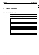
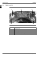
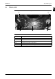
Introduction This chapter shows the switch box components.
Indoor units This chapter contains the following switch box layouts:
PCB layout See page
5.2–FCQ35, 50, 60, 71B 1–96
5.3–FCQ100, 125B 1–97
5.4–FCQ71, 100, 125 140D 1–98
5.5–FFQ25, 35, 50, 60B 1–99
5.6–FBQ35, 50, 60, 71, 100, 125B 1–100
5.7–FDQ125, 200, 250B 1–101
5.8–FHQ35, 50, 60, 71, 100, 125B 1–102
5.9–FUQ71, 100, 125B 1–103
5.10–FAQ71B 1–104
5.11–FAQ100B 1–105
5.12–FDEQ71, 100, 125B 1–106