
Specifications


Design flexibility
Main Features
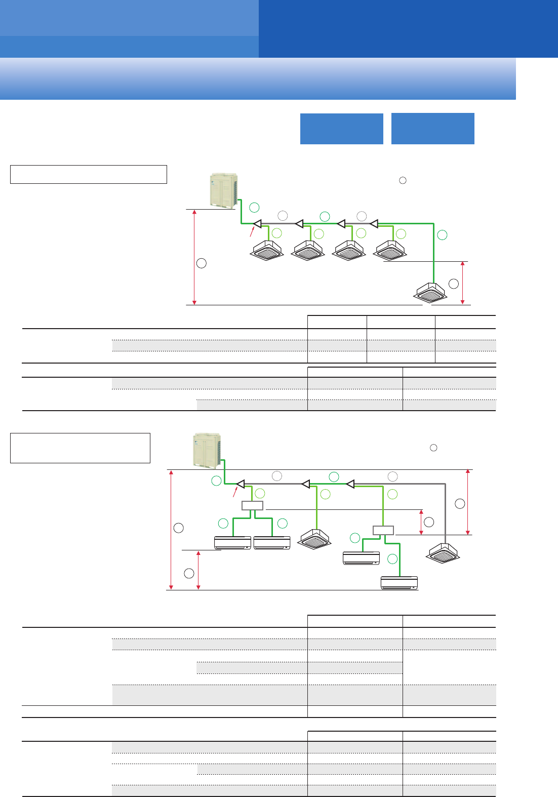
Long piping length offers flexibility during installation.
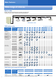
When only VRV indoor units are connected
When only VRV indoor units are connected
Maximum allowable
level difference
Maximum allowable
piping length
Maximum allowable
piping length
Minimum allowable piping length
Between the outdoor unit
and the indoor unit
Between the indoor units
Between the first indoor branch and the farthest indoor unit
Total piping length
Refrigerant piping length
15 m
—
—
j
a+b+c+d+e+f+g+h+i
a+b+c+d+i
b+c+d+i
100 m 125 m
250 m
40 m
Actual
piping length
Equivalent
piping length
Example
Level Difference Example
50 m
k
If the outdoor unit is above.
If the outdoor unit is below.
40 m
k
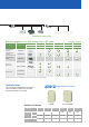
When a mixed combination of VRV and residential indoor units is connected
or when only residential indoor units are connected
Maximum allowable
level difference
Between the outdoor unit
and the indoor unit
Between BP unit
and indoor unit
Between the indoor units
Between BP units
Between the first indoor branch and the farthest BP unit or
between the first indoor branch and the farthest VRV indoor unit
Total piping length
Refrigerant piping length
Between outdoor unit and the first indoor branch
15 m
15 m
l
m
n
n
o
a+b+c+d+e+f+g+h+i+j+k
b+c+g, b+c+d
a+b+c+g+k, a+b+c+d
h, i, j, k
a
100 m
250 m
2 m–15 m
2 m–12 m
2 m–8 m
50 m
*1
5 m
Actual
piping length
Example
Level Difference Example
50 m
If the outdoor unit is above.
If the outdoor unit is below.
If indoor unit capacity index < 68.
If indoor unit capacity index is 68.
If indoor unit capacity index is 79.
40 m
40 m
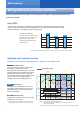
Long piping length
*1. When the piping length exceeds 20 m, the size of the main pipes (the gas side and the liquid side) must be increased. Please refer to Engineering
Data Book for details.
Max.
50 m
Max.
15 m
Max.
50 m
Max.
40 m
Max.
15 m
Max.
15 m
Actual piping length
Max. 100 m
Total piping length
Max. 250 m
a
o
l
n
d
c
b
g
f
e
First indoor branch
m
h i
a
i
j
k
d
c
b
h
g
f
e
First indoor branch
Colours in the diagram below are merely for identifying
pipes referenced with symbols such as a .
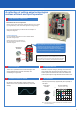
Colours in the diagram below are merely for identifying
pipes referenced with symbols such as a .
VRV: VRV indoor unit
RA: Residential indoor unit
BP: BP unit
When a mixed combination of VRV and
residential indoor units is connected
j
k
Between the outdoor unit and the BP unit
BP
RA RA
RA
RA
VRV
VRV
BP
7