
Service manual


General Outline: Indoor Units ESIE04-01
1–16 Part 1 – System Outline
3
11
4
5
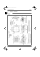
2.4 FFQ35~60BV1B
Outlook and
dimensions
The illustration below shows the outlook and the dimensions of the unit (mm).
NOTES:
1. Sticking location for manufacture’s label
Manufacture’s label for indoor unit : on the bell mouth inside suction grill
Manufacture’s label for decoration panel : on the inner frame inside suction grill
2. In case of using wireless remote controller, this position will be a signal receiver.
Refer to the drawing of wireless remote controller in detail.
3. When the temperature and humidity in the ceiling exceed 30°C and RH 80% or
the fresh air is inducted into the ceiling or the unit continues 24 hour operation,
an additional insulation (thickness 10mm or more of glasswool or polyethylene
form) is required.
4. Though the installation is acceptable up to maximum of 660mm square ceiling
opening, keep the clearance of 45mm or less between the main unit and the
ceiling opening so that the panel overlap allowance can be ensured.
Suspension bolt
Adjustable
A ARROW VIEW
or less
or less
NOTE) 4.
(Required space)
or more
From the floor side
or more
FOR HEIGHT INSTALLATION
or more
(Ceiling opening space)
(Suspension position)
(Ceiling opening space)
(Suspension position)
or less
NOTE) 2.
Drain connection side
Pipe connection side
*WHEN THE DISCHARGE GRILL IS CLOSED,
THE REQUIRED SPACE IS 200 mm OR MORE.
or more*
or more*
or more*
or more*
Outdoor air intake
(Direct connection)
Ceiling
hole
B ARROW VIEW
•REQUIRED SPACE
RZQ - Final.book Page 16 Monday, September 20, 2004 11:24 AM