
Service manual


PCB Layout ESIE04-01
1–102 Part 1 – System Outline
3
11
4
5
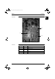
7.2 RZQ71B7V3B
Control PCB The illustration below shows the PCB connectors.
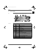
Connectors The table below describes the PCB connectors.
X64A
X18A
X17A
X19A
X20A
X6A
X12A
X77A
X22A
X1A
X3A
X26A
Connector Connected to Description
X1A X1M Terminal strip connector
X3A X205A on
inverter PCB
X6A For optional PCB KRP58M51
X12A Y1E Expansion valve
X17A R3T Discharge thermistor
X18A R4T Suction thermistor
X19A R2T Coil thermistor
X20A R1T Air thermistor
X22A Y1S 4-way valve
X26A Connector for spare part adaptor
X64A S1NPL Low pressure sensor
X77A For optional PCB KRP58M51
RZQ - Final.book Page 102 Monday, September 20, 2004 11:24 AM