
Series Installation Manual
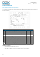
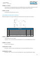
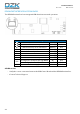
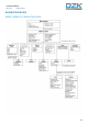
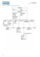
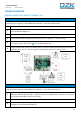
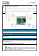
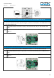
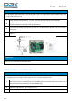
Table Of Contents
- Warnings, environmental policy, and certifications
- System description
- Description, installation and connection of the components
- Initial configuration
- Advanced configuration
- User settings – Wired Thermostat
- Zone settings
- Commissioning steps
- Exception codes
- Auto diagnostics
- Navigation guide
- Troubleshooting
- Wiring diagram
- Página en blanco

42
Installation Manual
Rev. 2.00 Date 01-2019
AUTO DIAGNOSTICS
DZK CONTROL BOARD AUTO DIAGNOSIS
The Zoning Box Control Board has LED’s integrated on the DZK Control Board that provide information of
abnormal conditions.
LED D3 does not blink
- Verify that the Control Board is powered.
- If the LED 11 is ON, the control board is faulty. Contact Technical Support.
Meaning
D1
Data reception from DZK BACnet Interface connector
Blinking
Green
D2
Data transmission from DZK BACnet Interface connector
Blinking
Red
D3
Main control board internal bus activity
Blinking
Green
D4
Data transmission from DZK connection bus
Blinking
Red
D5
Data reception from DZK connection bus
Blinking
Green
D6
1st Stage Aux. Heat Activated
Switches
Green
D7
2nd Stage Aux. Heat Activated
Switches
Green
D10
Wireless data packets reception
Switches
Green
D11
Main control board power
Solid
Red
D18
Wireless thermostat associated
Solid
Green
D19
Association channel: active
Solid
Red
Opening damper
On
Green
Closing damper
On
Red