
Series Installation Manual
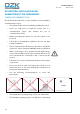
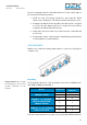
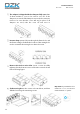
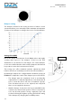
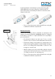
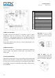
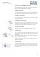
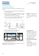
Table Of Contents
- Warnings, environmental policy, and certifications
- System description
- Description, installation and connection of the components
- Initial configuration
- Advanced configuration
- User settings – Wired Thermostat
- Zone settings
- Commissioning steps
- Exception codes
- Auto diagnostics
- Navigation guide
- Troubleshooting
- Wiring diagram
- Página en blanco

17
Installation Manual
Rev. 2.00 Date 01-2019
beginning with the central damper opening and ending with
damper No. 1 (Closest to the zoning box control board). The
reduced flow in the central dampers will increase the flow of the
dampers at the ends.
• The use of an anemometer verifies that the flow in each grille
is within the installation requirements.
Minimum Air (A-M)
Similarly, the zoning box allows a minimum air opening for each
damper, if needed. By default, the Position a damper is configured
in the full-close position. To adjust minimum air for any damper,
proceed as follows:
• Check that the dampers are wide open. To do so, set the
system to Stop user mode, from the Main Wired Thermostat.
• Perform the setting of the dampers by changing the lever
A-M position beginning with the central damper opening of
the box and ending with damper No. 1. (Closest to the
zoning box control board).
• With the damper open, place the handle A-M in the desired
open position. It has 4 positions (a, b, c and d) where position
“a" is fully closed and is "d" is the fully open.
• The use of an anemometer verifies that the flow in each grille
is within the installation requirements.
A-M lever