
Series Installation Manual
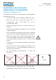
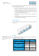
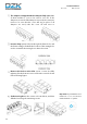
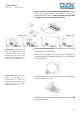
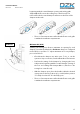
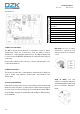
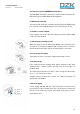
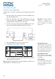
Table Of Contents
- Warnings, environmental policy, and certifications
- System description
- Description, installation and connection of the components
- Initial configuration
- Advanced configuration
- User settings – Wired Thermostat
- Zone settings
- Commissioning steps
- Exception codes
- Auto diagnostics
- Navigation guide
- Troubleshooting
- Wiring diagram
- Página en blanco

14
Installation Manual
Rev. 2.00 Date 01-2019
The adaptor is shipped with the dampers fully open. One
of them includes a cover to be used in case one of the
dampers is not used. If the damper is not used, the contractor
needs to be sure that the cover will stay in place. If all
dampers are used, take the cover off and store it.
Insert a sharp pointed object through the frame holes and
the frame sealing to facilitate the location of the setting holes
used to assemble the zoning box to the indoor unit.
Remove the indoor unit collar. Insert a screw (not fully
tightened) in the bottom corners of the indoor unit as shown
in the following figure:
Sit the zoning box on the screws as shown below, and then
affix the box using the remaining screws.
Important: If your DZK has holes
marked as "+" or "I", use the holes
marked with the "+" symbol