
Installation manual


English 12
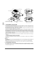
7-2 EXAMPLE FOR THE WHOLE SYSTEM
7-3 POWER CIRCUIT, SAFETY DEVICE AND CABLE REQUIREMENTS
• A power circuit (Refer to Table 3) must be provided for connection of the unit. This circuit must be protected
with the required safety devices, i.e. a main switch, a slow blow fuse on each phase and an earth leakage
circuit breaker.
• When using residual current operated circuit breakers, be sure to use a high-speed type (0.1 second or
less) 30mA rated residual operating current.
• Use copper conductors only.
• Use insulated wire for the power cord.
• Select the power supply cable type and size in accordance with relevant local and national regulations.
• Use vinyl cord with sheath or cable (2 wire) of AWG 18-16 for transmission wiring.
Table 3
MCA: Min. Circuit Amps (A); MFA: Max. Fuse Amps (A)
NOTES
• The above Table 3 of Electrical Characteristics refers to one BS unit.
• See the Engineering data book for other details.
7-4 WIRING EXAMPLE
• Here is shown a wiring example for one system transmission wiring.
• Connect terminals F1 and F2 (TO IN/D UNIT) on the control PCB (A1P) in the outside unit EL. COMPO.
BOX and terminals F1 and F2 (TO OUT/D UNIT) of the control PCB (A1P) of the first BS unit A.
Units Power supply
Model Type Hz Voltage Min. Max. MCA MFA
BSVQ36P
BSVQ60P
VJ 60 208~230 187 253 0.1 15
Power supply wiring
Transmission wiring
Switch
Fuse
Outside unit
Power supply
Power supply
Main switch
Main switch
BS unit
Indoor unit
Remote controller
Cooling/Heating selectable indoor unit
Cooling-dedicated
indoor unit