
User Guide
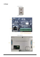
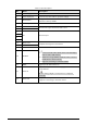
Table Of Contents

4
Table 2-1 Port description
No. Name Description
1 Power supply switch Turns on or off the Device.
2 Power input port Connects to power cable to get power supply.
3 Reset button
Long press the button for more than 5 s to restore the
detector to factory default.
4 Ethernet port Connects to network with network cable.
5 Alarm in +
Receives the signal of external alarm source.
6 Alarm in–
7
NC Reserved port.
8
9
10
11 Alarm out C
Outputs alarm signal to alarm device.
12 Alarm out NO
13 RS-485 B Controls external devices, such as PTZ.
●
Connect A and B cables (which both control RS-485) to
devices such as PTZ cameras.
●
If there are a large number of PTZ decoders, connect A
and B cables to 120 Ω resistors.
●
Supports connecting to a thermal camera.
14 RS-485 A
15 DB25 Signal port for metal detection.
16 Power in
Inputs 12 VDC power. Be sure to supply power as instructed
in the manual.
Device damage might occur if power is not supplied
correctly.
17 Power out
Outputs 12 VDC power.
Supports connecting to a thermal camera.