
User Guide
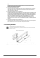
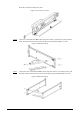
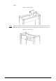
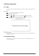
Table Of Contents

7
the beam, and then run the power cable.
Figure 3-2 Connect to host box
Step 4 Connect one end of the two DB25 cables and power cable to one detector panel, and then
attach the front beam and rear beam to the detector panel with four M8 × 8 screws.
Figure 3-3 Attach beams (1)
Step 5 Connect the other end of the two DB25 cables and power cable to one detector panel, and
then attach the front beam and rear beam to the detector panel with four M8 × 8 screws.
Figure 3-4 Attach beams (2)