Walk-through Metal Detector Quick Start Guide V1.0.
Foreword General This manual introduces the functions and operations of the walk-through metal detector (hereinafter referred to as the "Detector"). Safety Instructions The following signal words might appear in the manual. Signal Words Meaning Indicates a high potential hazard which, if not avoided, will result in death or serious injury. Indicates a medium or low potential hazard which, if not avoided, could result in slight or moderate injury.
● ● ● ● ● ● For detailed information, see the paper user’s manual, use our CD-ROM, scan the QR code or visit our official website. The manual is for reference only. Slight differences might be found between the electronic version and the paper version. All designs and software are subject to change without prior written notice. Product updates might result in some differences appearing between the actual product and the manual.
Important Safeguards and Warnings This chapter describes the contents covering proper handling of the Device, hazard prevention, and prevention of property damage. Read these contents carefully before using the Device, comply with them when using, and keep the manual well for future reference. Transportation Requirements Transport the Device under the allowed humidity and temperature conditions. Storage Requirements ● Keep the Device away from dampness, dust or soot.
Table of Contents Foreword ........................................................................................................................................................................................................I Important Safeguards and Warnings............................................................................................................................................ III 1 Overview ..............................................................................................
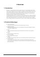
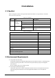
1 Overview 1.1 Introduction The device is a high-performance walk-through metal detector. It is light-weighted and has high metal detection sensitivity, strong anti-interference capabilities and stable performance. The device, made of high-strength special materials, is light-weighted and easy to transport and install. The device has a modular design and is manufactured on unified assembly lines, ensuring the good stability. It also delivers a simplicity and user-friendly interface.
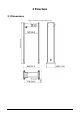
2 Structure 2.
2.
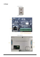
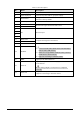
Table 2-1 Port description No. Name Description 1 Power supply switch Turns on or off the Device. 2 Power input port Connects to power cable to get power supply. 3 Reset button Long press the button for more than 5 s to restore the detector to factory default. 4 Ethernet port Connects to network with network cable. 5 Alarm in + 6 Alarm in– Receives the signal of external alarm source. 7 8 9 NC Reserved port.
3 Installation 3.1 Checklist After receiving the product, check against the table below. If there are any problems, contact the after-sales service personnel. Table 3-1 Checklist No.
The distance in this section is the recommended distance. The actual installation distance depends on the installation site conditions. ● Keep away from moving metal objects Large moving metal objects should be kept 0.5 m to 2 m away from the detector to avoid false alarms. Depending on the size of the metal object, the distance between the moving metal object and the detector might vary.
the beam, and then run the power cable. Figure 3-2 Connect to host box Step 4 Connect one end of the two DB25 cables and power cable to one detector panel, and then attach the front beam and rear beam to the detector panel with four M8 × 8 screws. Figure 3-3 Attach beams (1) Step 5 Connect the other end of the two DB25 cables and power cable to one detector panel, and then attach the front beam and rear beam to the detector panel with four M8 × 8 screws.
Step 6 Stand the Detector up. Figure 3-5 Stand the Detector up Step 7 Connect the power supply to the Detector, and then turn on the power switch to start the Detector. 3.4 Installing Thermal Camera Step 1 Use the Allen wrench to loosen the screws to disassemble the camera into three parts.
Step 2 Attach the camera base to its fixing bracket with three M4 × 16 screws. Figure 3-7 Attach camera base Step 3 Place the camera and its cover back in the original position. Figure 3-8 Install camera cover Step 4 Open the back cover of the detector, then take out the power cord from the accessories and connect it to the OUT port. Run the power cord and the camera cable through the opening of the back cover.
beams. Figure 3-10 Place camera Step 6 Connect the power cord and the camera cable to the corresponding ports of the camera. Move the camera to a suitable position and secure it with two to three M4 × 16 screws.
Step 7 Adjust the camera to a suitable angle. Figure 3-12 Done 3.5 Multiple Walk-through Detectors Site Installation When installing multiple devices, space the devices at least 50 cm, and also space the device and Xray security screening machine larger than 50 cm. This recommended spacing can make the little metal objects (such as coin) detected. If you install the devices with space smaller than 50 cm, there might be false alarm.
Figure 3-13 Multiple walk-through detectors site installation 3.6 Stabilizing Detector To make the Detector work normally, stabilize the Device before use by tightening the fixing screws.
4 Detector Configuration 4.1 Configuration Panel Figure 4-1 Configuration panel Table 4-1 Configuration panel description No. Description Displays number of passes, alarm times, signal strength bar, mode (normal, test, or alarm), current working frequency, volume and time. 1 ● With increase of the detected metals, the color will grow from green to red. There are 10 degrees: Degree 1-4 is green, degree 5-7 is yellow, and degree 810 is red. When the degree is up to 8, an alarm will be triggered.
No. Description Displays metal position indication with 18 indicators (red zone). 5 This function is only available on 18-zone detectors. 4.2 Remote Control You can set the parameters of the Device remotely through the remote control. Install the batteries before using the remote control. Figure 4-2 Remote control Table 4-2 Operation description No. Name Description 1 Power Turn on or off the Device. 2 Reset Press the button, and the number of passes and alarm times will be cleared.
4.3 Detector Operations 4.3.1 Login You can log in to the Device with the default password (000000). Change the password the first time you use it. Procedure Step 1 Step 2 Step 3 Connect the power supply, press the switch button. The main interface is displayed. Enter the password. Press or to move the cursor, and then press Press to move the cursor to OK, and the press to set the number. to confirm the password. If the password is wrong, the error note will be displayed.
Step 1 Log in to the Detector. For details, see "4.3.1 Login". Figure 4-4 Sensitivity setting Step 2 Press or to move the cursor to Sensitivity, and then press to go to the sensitivity setting interface. Figure 4-5 Set sensitivity Step 3 Select the zone that needs to be set, and then set sensitivity. Press or to move the cursor to a zone (for example, L1Zo), and then press to set the value.
Figure 4-6 Setting security level Step 4 Press to move the cursor to OK, and then press to save the setting. Result When both the defined threshold of security level and sensitivity are reached, an alarm will be triggered. When both the defined threshold of security level and sensitivity are reached, an alarm will be triggered. For the details of sensitivity, see #d274e7a1026. 4.3.3 Setting Frequency Electromagnetic interference from ambient environment varies with different frequencies.
Figure 4-7 Frequency setting Step 3 Set the frequency. or to move the cursor, and press to enable ● Auto search frequency: Press the auto search frequency function. The Device will set the suitable working frequency automatically. If the working frequency still needs to be adjusted, you can set the value manually. Do not pass or approach to the detector during auto searching. Alarm might be triggered during auto searching.
Step 1 Log in to the Detector. For details, see "4.3.1 Login". Step 2 Press or to move the cursor to System, and then press . Figure 4-9 System Step 3 Press or to move the cursor to Alarm, and then press . Figure 4-10 Alarm Step 4 Press or to move the cursor to ON, and then press to enable the temperature overlay function. Press , ON becomes OFF, and then press to disable the function. Figure 4-11 Set Temp Overlay Step 5 Press or to move the cursor to OK, and then press 19 .
the total number of temperature alarms are displayed on the screen. When the body temperature is normal, the words on the screen are white and the duration is 1 s. When the body temperature is abnormal, the words are red and the duration is 3 s.
5 Configuring Camera With a thermal camera, the Detector supports temperature monitoring. The detection rules are set by default, but you can change it to meet your preference. For details, see Thermal Hybrid Camera_Web Operation Manual. 5.1 Logging in to Camera Step 1 Step 2 Open IE browser (IE7 and later), enter the IP address of the device (192.168.1.108 by default) in the address bar and press the Enter key. Enter the username and password. Step 3 The username is admin by default. Click Login. 5.
5.3 Configuring Temperature Monitoring Thermal temperature monitoring is enabled. For details, see "5.2 Enabling Smart Plan". Step 1 Select Setting > Smart Thermal > Temp Monitoring. Step 2 Step 3 Click Draw Rule to draw a detection area. Make sure that the lower border of the detection area is close to the general height of people's shoulders. The upper border can be next to the upper edge of the thermal image. Select the Enable check box. It is enabled by default.
Step 4 Configure thermal temperature monitoring parameters. Table 5-1 Description of temperature monitoring parameter Parameter Description Define a period during which the alarm settings are valid. 1. Click Setting, and the period setting interface is displayed. 2. Configure period. Period ● Method 1: Press and drag the left mouse button on the time line. ● Method 2: Click Setting for the day in the week you want to configure, and then configure periods as needed (6 periods are available). 3.
Figure 5-3 Temperature monitoring Step 2 Step 3 Select the display mode of the channel. ● Visual: It is selected by default. ● Thermal: When the light is not good (such as with black light or the light is too dim), we recommend you selecting Thermal. ● Schedule: Select Schedule and then configure the schedule. The two channels will switch automatically to the configured schedule. (Optional) Configure Snap Angle Filter. ● 1: The camera detects frontal faces only. ● 90: The camera detects side faces only.
Appendix 1 Cybersecurity Recommendations Mandatory actions to be taken for basic equipment network security: 1. Use Strong Passwords Please refer to the following suggestions to set passwords: ● The length should not be less than 8 characters. ● Include at least two types of characters; character types include upper and lower case letters, numbers and symbols. ● Do not contain the account name or the account name in reverse order. ● Do not use continuous characters, such as 123, abc, etc.
reducing the risk of ARP spoofing. 8. Assign Accounts and Privileges Reasonably According to business and management requirements, reasonably add users and assign a minimum set of permissions to them. 9. Disable Unnecessary Services and Choose Secure Modes If not needed, it is recommended to turn off some services such as SNMP, SMTP, UPnP, etc., to reduce risks.