
User Guide

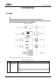
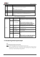
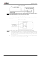
Table Of Contents

Quick Start Guide
3
Alarm input Figure 1-2
Connect alarm output device to the alarm output end of the I/O port. The alarm output is Step 2
relay switch output, which can only connect to NO alarm devices.
The ALARM_OUT port and the ALM_OUT_GND port with the same number constitute a
switch for alarm output, see Figure 1-3. The switch is open normally and closes when there is
alarm output.
Alarm output Figure 1-3
Log in web interface, and configure alarm input and alarm output in alarm setting. Step 3
The alarm input in the web interface is corresponding to the alarm input end of the I/O
port. There will be high level and low level alarm signal generated by the alarm input
device when alarm occurs, set the input mode to NO if the signal is high level and to NC
if the signal is low level.
The alarm output in the web interface is corresponding to the alarm output end of the
device, which is also the alarm output end of the I/O port.