
Instruction Manual

22
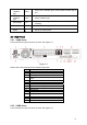
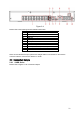
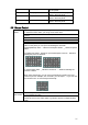
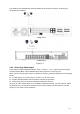
Figure 2-4
Please refer to the following sheet for detailed information.
1 Video input
2 Audio input
3 Audio output
4 Video CVBS output
5 USB port
6 Network port
7 HDMI port
8 RS232 port
9 Video VGA output
10 Alarm input/alarm output/RS485 port
11 Power button
12 Power socket
When connect the Ethernet port, please use straight cable to connect the PC and use the
crossover cable to connect to the switcher or router.
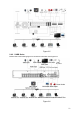
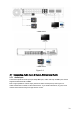
2.3 Connection Sample
2.3.1 4 HDD Series
Please refer to X281H281H281HFigure 2-5 for connection sample.