
Manual

24
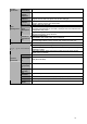
Status
indication
light
Status
If there is Fn indication light, current status indication light is
null.
Power
indication
light
PWR Power indication light
Record light 1-16
System is recording or not. It becomes on when system is
recording.
IR Receiver IR It is to receive the signal from the remote control.
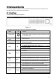
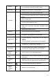
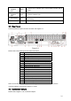
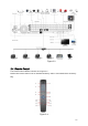
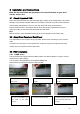
2.2 Rear Panel
This series DVR rear panel is shown as below. See Figure 2-2.
Figure 2-2
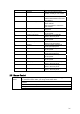
Please refer to the following sheet for detail information.
1 Power button
2 Power input port
3 Fan
4 Loop video output
5 1
st
to 4
th
-channel audio input
6 Video input
7 DB25 port (5
th
to 16
th
-channel audio input port)
8 Audio output
9 Bidirectional talk input port
10 Bidirectional talk output port
11 Network port
12 eSATA port
13 RS232 port
14 USB port
15 HDMI port
16 Video VGA output
17 Alarm input/alarm output/RS485 port
18 Video CVBS output
19 Video matrix output
When connect the Ethernet port, please use straight cable to connect the PC and use the
crossover cable to connect to the switcher or router.
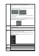
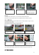
2.3 Connection Sample
Please refer to X281H281H281HFigure 2-3X for connection sample.