
User's Manual

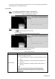


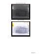
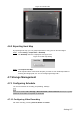


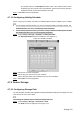
Table Of Contents
- Cybersecurity Recommendations
- Regulatory Information
- Foreword
- 1 Product Introduction
- 2 Basic Settings
- 3 Daily Operation
- 3.1 Live
- 3.2 PTZ
- 3.2.1 Bullet Camera
- 3.2.2 Dome Camera
- 3.2.2.1 Configuring Protocol
- 3.2.2.2 Configuring PTZ Functions
- 3.2.2.2.1 Configuring Preset
- 3.2.2.2.2 Configuring Tour
- 3.2.2.2.3 Configuring Scan
- 3.2.2.2.4 Configuring Pattern
- 3.2.2.2.5 Configuring Pan
- 3.2.2.2.6 Configuring PTZ Speed
- 3.2.2.2.7 Configuring Idle Motion
- 3.2.2.2.8 Configuring Power Up
- 3.2.2.2.9 Configuring Time Task
- 3.2.2.2.10 Restarting PTZ Manually
- 3.2.2.2.11 Restoring PTZ to the Default Settings
- 3.2.2.3 Operating PTZ
- 3.2.2.4 Configuring Preset Backup
- 3.3 Playback
- 3.4 Reports
- 3.5 Alarm
- 4 Setting
- 4.1 Configuring Camera
- 4.1.1 Configuring Lens
- 4.1.2 Configuring Video Parameters
- 4.1.3 Configuring Audio Parameters
- 4.2 Configuring Network
- 4.3 Peripheral
- 4.4 Smart Thermal
- 4.5 Event
- 4.6 Temperature Measuring Settings
- 4.7 Storage Management
- 4.8 System Management
- 4.1 Configuring Camera
- 5 System Maintenance
- 6 Additional Accessing Methods
Setting 124
Parameters
Description
Alarm Condition
Contains "lower", "matched" and "higher."
Alarm Threshold
Temperature
Temperature of triggering an alarm. Ranges from 0 – 550 °C .
Click Save to finish configuration. Step 3
On the left-side live image, you can view temperature contrast results of the object you
have selected.
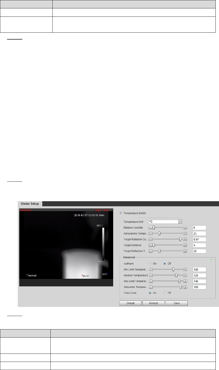
4.6.2 Configuring Global Setup
You can enable Temperature Switch, Isotherm and Color Code.
Temperature Switch: A switch with which you can enable or disable temperature testing
rules. Enable the Temperature Switch and the temperature testing rules you have set will
be displayed on surveillance images.
Isotherm: Used to highlight an object in images of high brightness. Isotherm is based on
median temperature, with highest temperature and lowest temperature as its range. The
part of an object whose temperature is higher than floor temperature will be represented in
a bright color and the part of an object whose temperature is lower than floor temperature
will be represented in a black/white color.
Color Code: Enable this function, and a color code is displayed on the right side of
surveillance images to show change of color between minimum temperature and
maximum temperature.
Select Setting > Temperature > Global Setup. Step 1
The Global Setup interface is displayed. See Figure 4-68.
Global setup Figure 4-68
Configure the global setup parameters. See Table 4-40 for details. Step 2
Table 4-40 Parameter description of global setup
Parameter
Description
Temperature
Switch
Select the check box to enable this function.
Temperature Unit
Includes °C and °F.
Relative Humidity
Relative humidity of environment. Ranges from 0RH – 100 %RH.