
User's Manual
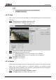
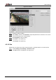

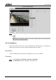

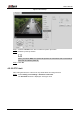
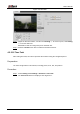

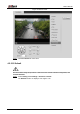
Table Of Contents
- Foreword
- Important Safeguards and Warnings
- 1 Overview
- 2 Configuration Flow
- 3 Device Initialization
- 4 Basic Configuration
- 4.1 Login
- 4.2 Live
- 4.3 PTZ Operation
- 4.4 Playback
- 4.5 Camera
- 4.5.1 Conditions
- 4.5.2 Setting Video Parameters
- 4.5.2.1 Video
- 4.5.2.2 Snapshot
- 4.5.2.3 Overlay
- 4.5.2.3.1 Configuring Privacy Masking
- 4.5.2.3.2 Configuring Channel Title
- 4.5.2.3.3 Configuring Time Title
- 4.5.2.3.4 Configure Text Overlay
- 4.5.2.3.5 Configure Font Attribute
- 4.5.2.3.6 Configure Picture Overlay
- 4.5.2.3.7 Configure Custom Overlay
- 4.5.2.3.8 Configuring OSD Info
- 4.5.2.3.9 Configuring Counting
- 4.5.2.3.10 Configuring Structured Statistics
- 4.5.2.3.11 Configuring Ranging
- 4.5.2.3.12 Configuring ANPR
- 4.5.2.3.13 Configuring Face Statistics
- 4.5.2.4 ROI
- 4.5.2.5 Path
- 4.5.3 Audio
- 4.6 Network
- 4.7 Storage
- 4.8 System
- 5 Event
- 5.1 Setting Alarm Linkage
- 5.2 Setting Smart Track
- 5.3 Setting Panoramic Calibration
- 5.4 Setting Video Detection
- 5.5 Setting Smart Motion Detection
- 5.6 Setting Audio Detection
- 5.7 Setting Smart Plan
- 5.8 Setting IVS
- 5.9 Setting Crowd Map
- 5.10 Setting Face Recognition
- 5.11 Setting Face Detection
- 5.12 Setting People Counting
- 5.13 Setting Heat Map
- 5.14 Setting Stereo Analysis
- 5.15 Setting ANPR
- 5.16 Setting Video Structuralization
- 5.17 Setting Relay-in
- 5.18 Setting Abnormality
- 6 Maintenance
- Appendix 1 Cybersecurity Recommendations

User’s Manual
29
PTZ limit Figure 4-16
Adjust the direction buttons, and then click Setting ① to set the up line; click Setting Step 2
② to set the down line.
Click Live to view the configured up line and down line.
Select the Enable check box to enable the PTZ limit function. Step 3
4.3.2.10 Time Task
After setting time task, the camera performs the motions during the configured period.
Preparation
You have configured the PTZ motions, including preset, scan, tour, and pattern.
Procedure
Select Setting > PTZ settings > Function > Time Task. Step 1
The Time Task interface is displayed. See Figure 4-17.