
User's Manual
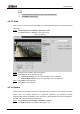
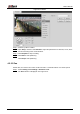


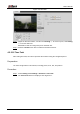

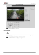
Table Of Contents
- Foreword
- Important Safeguards and Warnings
- 1 Overview
- 2 Configuration Flow
- 3 Device Initialization
- 4 Basic Configuration
- 4.1 Login
- 4.2 Live
- 4.3 PTZ Operation
- 4.4 Playback
- 4.5 Camera
- 4.5.1 Conditions
- 4.5.2 Setting Video Parameters
- 4.5.2.1 Video
- 4.5.2.2 Snapshot
- 4.5.2.3 Overlay
- 4.5.2.3.1 Configuring Privacy Masking
- 4.5.2.3.2 Configuring Channel Title
- 4.5.2.3.3 Configuring Time Title
- 4.5.2.3.4 Configure Text Overlay
- 4.5.2.3.5 Configure Font Attribute
- 4.5.2.3.6 Configure Picture Overlay
- 4.5.2.3.7 Configure Custom Overlay
- 4.5.2.3.8 Configuring OSD Info
- 4.5.2.3.9 Configuring Counting
- 4.5.2.3.10 Configuring Structured Statistics
- 4.5.2.3.11 Configuring Ranging
- 4.5.2.3.12 Configuring ANPR
- 4.5.2.3.13 Configuring Face Statistics
- 4.5.2.4 ROI
- 4.5.2.5 Path
- 4.5.3 Audio
- 4.6 Network
- 4.7 Storage
- 4.8 System
- 5 Event
- 5.1 Setting Alarm Linkage
- 5.2 Setting Smart Track
- 5.3 Setting Panoramic Calibration
- 5.4 Setting Video Detection
- 5.5 Setting Smart Motion Detection
- 5.6 Setting Audio Detection
- 5.7 Setting Smart Plan
- 5.8 Setting IVS
- 5.9 Setting Crowd Map
- 5.10 Setting Face Recognition
- 5.11 Setting Face Detection
- 5.12 Setting People Counting
- 5.13 Setting Heat Map
- 5.14 Setting Stereo Analysis
- 5.15 Setting ANPR
- 5.16 Setting Video Structuralization
- 5.17 Setting Relay-in
- 5.18 Setting Abnormality
- 6 Maintenance
- Appendix 1 Cybersecurity Recommendations

User’s Manual
26
PTZ speed Figure 4-13
Select the PTZ speed: Low, Middle, and High. Step 2
Speed under the direction buttons refers to the rotation angle of the PTZ camera for
each press of the direction button.
4.3.2.7 Idle Motion
Idle motion means that the PTZ camera implements the operation which is configured in
advance when it does not receive any valid command within the set time
Preparation
You have configured the PTZ motions, including preset, scan, tour, or pattern.
Procedure
Select Setting > PTZ settings > Function > Idle Motion. Step 1
The Idle Motion interface is displayed. See Figure 4-14.