User’s Manual Network Camera Web 3.0 Operation Manual ZHEJIANG DAHUA VISION TECHNOLOGY CO., LTD. V2.0.2 ZHEJIANG DAHUA VISION TECHNOLOGY CO., LTD. V1.0.
User’s Manual Foreword General This manual introduces the functions, configuration, general operation, and system maintenance of network camera. Safety Instructions The following categorized signal words with defined meaning might appear in the manual. Signal Words Meaning Indicates a medium or low potential hazard which, if not avoided, could result in slight or moderate injury.
User’s Manual About the Manual The manual is for reference only. If there is inconsistency between the manual and the actual product, the actual product shall prevail. We are not liable for any loss caused by the operations that do not comply with the manual. The manual would be updated according to the latest laws and regulations of related regions. For detailed information, see the paper manual, CD-ROM, QR code or our official website.
User’s Manual Important Safeguards and Warnings Electrical Safety All installation and operation shall conform to your local electrical safety codes. The power source shall conform to the Safety Extra Low Voltage (SELV) standard, and supply power with rated voltage which conforms to Limited power Source requirement according to IEC60950-1. Note that the power supply requirement is subject to the device label. Make sure that the power supply is correct before operating the device.
User’s Manual It is recommended to ground the device to enhance reliability. Do not touch the image sensor (CMOS) directly. Dust and dirt could be removed with air blower, or you can wipe the lens gently with soft cloth that is moistened with alcohol. You can clean the device body with soft dry cloth, and for stubborn stains, use the cloth with mild detergent.
User’s Manual Table of Contents Foreword .................................................................................................................................................... I Important Safeguards and Warnings .................................................................................................... III 1 Overview ................................................................................................................................................. 1 1.1 Introduction ....
User’s Manual 4.6.12 Access Platform .............................................................................................................. 86 4.7 Storage ........................................................................................................................................ 89 4.7.1 Setting Storage Plan ......................................................................................................... 89 4.7.2 Setting Schedule...................................................
User’s Manual 5.13.2 Viewing Heat Map Report ............................................................................................. 171 5.14 Setting Stereo Analysis ........................................................................................................... 172 5.14.1 Setting Rules for Stereo Analysis ................................................................................. 172 5.14.2 Calibration Configuration ....................................................................
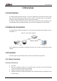
User’s Manual 1 Overview 1.1 Introduction IP camera (Internet Protocol camera), is a type of digital video camera that receives control data and sends image data through internet. They are commonly used for surveillance, requiring no local recording device, but only a local area network. IP camera is divided into single-channel camera and multi-channel camera according to the channel quantity. For multi-channel camera, you can set the parameters for each channel. 1.
User’s Manual Record abnormality of monitoring image for subsequent view and processing. Configure coding parameters, and adjust live view image. Record Auto record as schedule. Play back recorded video and picture as needed.. Download recorded video and picture. Alarm linked recording. Account Add, modify and delete user group, and manage user authorities according to user group. Add, modify and delete user, and configure user authorities. Modify user password. 1.3.
User’s Manual IVS Tripwire, intrusion, abandoned object, moving object, fast moving, parking detection, people gathering, and loitering detection. When an alarm is triggered, the system performs linkages such as recording, alarm output, sending email, PTZ operation, and snapshot. Crowd Map View crowd distribution in real time for the timely arm to avoid accidents like stampede.
User’s Manual ANPR Recognize plate number in detection area, and display the related information on live interface. When an alarm is triggered, the system links alarm output and snapshot. Video Structuralization Snap people, non-motor vehicle and vehicle, and display the related information on the live interface. When an alarm is triggered, the system links alarm output. Alarm Setting The alarm is triggered when an external alarm input device inputs alarm.
User’s Manual 2 Configuration Flow For the device configuration flow, see Figure 2-1. For details, see Table 2-1. Configure the device according to the actual situation. Figure 2-1 Configuration flow Table 2-1 Description of flow Configuration Description Reference Login Open IE browser and enter IP address to log in to the web interface, The camera IP address is 192.168.1.108 by default. 4.1 Login Initialization Initialize the camera when you use it for the first time.
User’s Manual 3 Device Initialization Device initialization is required for the first use. This manual is based on the operation on the web interface. You can also initialize device through ConfigTool, NVR, or platform devices. To ensure the device safety, keep the password properly after initialization and change the password regularly. When initializing device, keep the PC IP and device IP in the same network.
User’s Manual Figure 3-2 End-user license agreement Step 4 Select the I have read and agree to all terms check box, and then click Next. The Easy4ip interface is displayed. See Figure 3-3. Figure 3-3 Easy4ip Step 5 You can register the camera to Easy4ip, select the check box as needed, and then click Next. The Online Upgrade interface is displayed. See Figure 3-4.
User’s Manual Figure 3-4 Online upgrade Step 6 Select the upgrading method as needed. If you select Auto-check for updates, the system checks new version once a day automatically. There will be system notice on Upgrade interface and Version interface if any new version is available. Select Setting > System > Upgrade > Online Upgrade, and you can enable the auto-check function. Step 7 Click Save. Device initialization is completed.
User’s Manual 4 Basic Configuration The chapter introduces the basic configuration, including login, live view, PTZ operation, playback operation, camera configuration, network configuration, storage configuration and system configuration. 4.1 Login This section introduces how to log in to and log out of the web interface. This section takes IE Explorer 9 as an example. You need to initialize the camera before logging in to the web interface. For details, see "3 Device Initialization.
User’s Manual Setting: Click Setting, and you can configure the basic and intelligent functions of the camera. For the camera with multiple channels, through selecting channel numbers, you can set the parameters of the channels. Alarm: Click Alarm, and you can subscribe and view alarm information. Logout: Click Logout to go to login interface. The system will sleep automatically after idling for a period of time. Figure 4-2 Live 4.
User’s Manual Figure 4-3 Live Table 4-1 Description of function bar No. Function Description 1 Encode bar Sets stream type and protocol. 2 Live view Displays the real-time monitoring image. 3 Live view function bar Functions and operations in live viewing. 4 Window adjustment bar Adjustment operations in live viewing. 4.2.2 Encode bar For encode bar, see Figure 4-4.
User’s Manual Table 4-2 Description of live view function bar Icon Function Description Manually position the tracking speed dome to the selected location of corresponding panoramic camera. Click the icon and click or select randomly on the image of panoramic camera channel, the tracking speed dome will automatically position the selected location.
User’s Manual Icon Function Description image to zoom in; right-click on the image to resume the original size. In zoom in state, drag the image to check other area. Click the icon, and then scroll the mouse wheel in the video image to zoom in or out. Click the icon to capture one picture of the current image, and it will be saved to the configured storage path. Snapshot About viewing or configuring storage path, see "4.5.2.5 Path.
User’s Manual Table 4-3 Description of adjustment bar Icon Function Description Click the icon, and then the Image Adjustment interface is displayed at the right side of the Live interface. You can adjust brightness, contrast, hue, and saturation. The adjustment is only available on the web interface, and it does not adjust the camera parameters. (Brightness adjustment): Adjusts the overall image brightness, and changes the value when the image is too bright or too dark.
User’s Manual Icon Function Description PTZ Click the icon, and the PTZ control panel is displayed at the right side of the Live interface. You can control and call PTZ function. For details, see "4.3.3 Calling PTZ." Zoom and Focus Adjust focal length to zoom in and out video image. Click the icon, and the Zoom and Focus configuration interface is displayed at the right side of the Live interface. You can control and call PTZ function. For details, see "4.2.4.2 Zoom and Focus.
User’s Manual Figure 4-5 Zoom and focus Table 4-4 Description of zoom and focus Parameter Description Zoom Changes the focal length of the camera to zoom in or out the image. 1. Set the Speed value. The Speed is the adjustment range in one click. The larger the value is, the more the image would zoom in or out in one click. 2. Click or hold + /– button, or drag the slider to adjust zoom. Focus Adjusts the optical back focal length to make the image clearer. 1. Set the Speed value.
User’s Manual 4.2.4.3 Fisheye You can select the installation mode, display mode and VR mode of fisheye devices as needed. For details, see Table 4-5. Install Mode: Select the installation mode according to the actual situation. Display Mode: Select the display mode of live view. VR Mode: Select VR mode to display images in stereo mode. Figure 4-6 Fisheye Table 4-5 Description of fisheye configuration Parameter Description Installation mode Includes ceiling mount, wall mount, and ground mount.
User’s Manual Parameter Ceiling/Wall/Ground mount Description Original The original image before correction. image 1P+1 2P 360° rectangular panoramic image screen + independent sub-screens. You can zoom or drag the image in all the screens. You can move the start point (left and right) on rectangular panoramic image screen. Two associated 180° rectangular image screens, and at any time, the two screens form a 360° panoramic image. It is also called dual-panoramic image.
User’s Manual Parameter Description 1P+8 1P 1P+3 Original image screen + eight independent sub-screens. You can zoom or drag the image in all the screens. You can rotate the image on the original image screen to change the start point. 180°rectangular panoramic image screen (from left to right). You can drag the image in all the screens (up and down) to adjust the vertical view. 180° rectangular panoramic image screen + three independent sub-screens.
User’s Manual Parameter Description Display the distortion panorama in 360°circularity. Cylinder Asteroid You can drag the image in upper/lower/left/right direction. Press I to display the panorama, and press O to return to the orignal size. Press S to rotate the image in anticlockwise direction, and press E to stop the rotation. Scroll the mouse wheel to zoom the image. You can drag the image in upper/lower/left/right direction.
User’s Manual Step 2 Select the PTZ protocol. Step 3 Click OK. 4.3.2 Configuring PTZ Function 4.3.2.1 Preset Preset means a certain position that the camera can make quick orientation to. It includes PTZ pan and tilt angles, camera focus, and location. Step 1 Select Setting > PTZ settings > Function > Preset. The Preset interface is displayed. See Figure 4-8.
User’s Manual 4.3.2.2 Tour Tour means a series of movements that the camera makes along several presets. Preparation You have set several presets. Procedure Step 1 Select Setting > PTZ settings > Function > Tour. The Tour interface is displayed. See Figure 4-9. Figure 4-9 Tour Step 2 Click Add ① to add tour. Double-click the tour name to edit the name. Step 3 Click Add ② to add preset. Double-click the duration to set the duration. Step 4 Select the tour mode.
User’s Manual If you operate PTZ during tour, the camera will stop tour. Click Stop to stop touring. 4.3.2.3 Scan Scan means the camera moves horizontally at a certain speed between the configured left and right limits. Step 1 Select Setting > PTZ settings > Function > Scan. The Scan interface is displayed. See Figure 4-10. Figure 4-10 Scan Step 2 Select the scan number, and set the speed. Step 3 Click Setup to set left limit and left limit.
User’s Manual Figure 4-11 Pattern Step 2 Select the pattern number. Step 3 Click Setup, and then click Start Rec. Adjust the parameters of direction, zoom, focus and iris according to the actual situation. Step 4 Click Stop Rec to stop recording. Step 5 Click Start to start patterning. Click Stop to start patterning. 4.3.2.5 Pan Enable Pan, the camera can realize continuous 360°horizontal rotation at a certain speed. Step 1 Select Setting > PTZ settings > Function > Pan. The Pan interface is displayed.
User’s Manual Figure 4-12 Pan Step 2 Set the pan speed and click Start, and the camera starts horizontal rotation. Click Stop to stop rotation. 4.3.2.6 PTZ Speed PTZ speed means the rotation speed of the PTZ camera during touring, pattern, or auto tracking. Step 1 Select Setting > PTZ settings > Function > PTZ Speed. The PTZ Speed interface is displayed. See Figure 4-13.
User’s Manual Figure 4-13 PTZ speed Step 2 Select the PTZ speed: Low, Middle, and High. Speed under the direction buttons refers to the rotation angle of the PTZ camera for each press of the direction button. 4.3.2.7 Idle Motion Idle motion means that the PTZ camera implements the operation which is configured in advance when it does not receive any valid command within the set time Preparation You have configured the PTZ motions, including preset, scan, tour, or pattern.
User’s Manual Figure 4-14 Idle motion Step 2 Select the Enable check box to enable the idle motion function. Step 3 Select the idle motion and set the idle time. You need to select the corresponding number for some selected idle motions, such as Preset001. Step 4 Click Save 4.3.2.8 PowerUp After setting Powerup motion, the camera will perform the configured motion after it is power on. Preparation You have configured the PTZ motions, including preset, scan, tour, or pattern.
User’s Manual Figure 4-15 PowerUp Step 2 Select the Enable check box to enable the power up function. Step 3 Select the power up motion. When you select Auto, the system will perform the last motion that is executed for more than 20 s before power-off. Step 4 Click OK. 4.3.2.9 PTZ Limit After setting PTZ limit, the camera can only rotate within the configured area. Step 1 Select Setting > PTZ settings > Function > PTZ Limit. The PTZ Limit interface is displayed. See Figure 4-16.
User’s Manual Figure 4-16 PTZ limit Step 2 Adjust the direction buttons, and then click Setting ① to set the up line; click Setting ② to set the down line. Click Live to view the configured up line and down line. Step 3 Select the Enable check box to enable the PTZ limit function. 4.3.2.10 Time Task After setting time task, the camera performs the motions during the configured period. Preparation You have configured the PTZ motions, including preset, scan, tour, and pattern.
User’s Manual Figure 4-17 Time task Step 2 Select the Enable check box to enable time task function. Step 3 Select the time task number. Step 4 Select the time task action. You need to select the corresponding action number for some selected time task actions. Step 5 Set the auto home time in AutoHome. AutoHome: When you call PTZ, the time task will be interrupted. After setting AutoHome time, the camera will resume the time task automatically.
User’s Manual Figure 4-18 PTZ restart Step 2 Click PTZ Restart to restart PTZ. 4.3.2.12 Default Be careful when doing this operation. It will restore the camera to default configuration, and result in data loss. Step 1 Select Setting > PTZ settings > Function > Default. The Default interface is displayed. See Figure 4-19.
User’s Manual Figure 4-19 Default Step 2 Click Default and the PTZ function is restored to default. 4.3.3 Calling PTZ Click on Live interface, and the PTZ configuration panel is displayed. You can control PTZ and call PTZ function. 4.3.3.1 PTZ Control You can rotate device, zoom image, and adjust iris through PTZ control or virtual joystick. See Figure 4-20 and Figure 4-21.
User’s Manual Figure 4-20 PTZ control Figure 4-21 Joystick : Rotate PTZ direction through direction button. PTZ supports eight directions: left/right/up/down/upper left/upper right/bottom left/bottom right. Click , and draw a box in the image, PTZ will rotate, focus and quickly position the defined scene. : Rotate PTZ direction through joystick. Select and hold direction that you need, then PTZ will move to the defined direction.
User’s Manual Speed: Measure the rotation speed. The higher the speed value is, the faster the speed becomes. Zoom, focus and iris: Click or to adjust zoom, focus and iris. 4.3.3.2 PTZ Function Select the PTZ function from the drop-down list to call the corresponding functions, including Scan, Preset, Tour, Pattern, Pan, Go to, Assistant and Light Wiper. See Figure 4-22. For details, see Table 4-6. Before calling PTZ function, see "4.3.2 Configuring PTZ Function" to configure PZT function.
User’s Manual Parameter Description Light/Wiper Set the light or wiper of the camera. Click Enable to enable light/wiper function. Click Disable to disable light/wiper function. 4.4 Playback This section introduces playback related functions and operations, including video playback and picture playback. Before playing back video, configure record time range, record storage method, record schedule and record control. For details, see "5.1.1.2.1 Setting Record Plan.
User’s Manual Figure 4-24 Picture playback Table 4-7 Playback interface description No Function Description Click Fisheye , you can select display mode according to the installation mode during playback. This function is only available on fisheye cameras. 1 Click , intelligent rules and object detection box are displayed. It is enabled by default. Rules Info Rules Info is valid only when you enabled the rule during recording. Controls the sound during playback. 2 Sound : Mute mode.
User’s Manual No Function Description Controls playback. 3 : Click the icon to play back recorded videos. : Click the icon to stop playing back recorded videos. : Click the icon to play the next frame. Play control bar When you enable the function of playing video by frame, you need to stop playback. : Click the icon to slow down the playback. : Click the icon to speed up the playback. 4 Progress bar Displays the record type and the corresponding period.
User’s Manual No Function 9 Time format progress bar Description Includes 4 time formats: , , , of . Take as an example, the whole progress stands for 24 hours. 4.4.2 Playing back Video or Picture This section introduces the operation of video playback and picture playback. This section takes video playback as an example. Step 1 Select dav from the Record Type drop-down list and SD card from the Data Src drop-down list. See Figure 4-25.
User’s Manual Figure 4-27 Specific event types Step 3 Select the month and year of the video that you want to play. Those dates with blue color indicate there were videos recorded in those days. Step 4 Play video. Click in the control bar. The system plays the recorded video of the selected date (in the order of time). Click any point in the colored area on the progress bar. See Figure 4-28. The playback starts from that moment.
User’s Manual Figure 4-29 Playback file list (1) 4.4.3 Clipping Video Step 1 Click , the video files of the selected date are listed. Step 2 Select dav or mp4 in Download Format. Step 3 Click on the progress bar to select the start time of the target video, and then click . See Figure 4-30. Figure 4-30 Clipping video Step 4 Click again on the progress bar to select the end time of the target video, and then click . Step 5 Click to download the video.
User’s Manual 4.4.4 Downloading Video or Picture Download video or picture to a defined path. You can download single video or picture file, or download them in batches. This section takes downloading video as an example. Playback and downloading at the same time is not supported. Operations might vary with different browsers, and the actual product shall prevail. For details of viewing or setting storage path, see "4.5.2.5 Path." 4.4.4.
User’s Manual Figure 4-31 Batch download Step 2 Select the record type, set the start time and end time, and then click Search. The searched files are listed. Step 3 Select the files to be downloaded, select dav or mp4 from Format drop-down list, and then set the storage path. Click Download. The system starts to download the file to the configured path. When downloading picture, you do not need to select the download format. 4.
User’s Manual You can select from normal, day and night mode to view the configuration and the effect of the selected mode, such as picture, exposure, and backlight. Camera with PZT function supports zoom, focus and iris operations. See Figure 4-33. Configure speed, click direction button, and to adjust the direction, zoom, focus and iris and so on, to adjust the camera to the proper position.
User’s Manual Figure 4-33 Camera conditions (PTZ camera) 4.5.1.1.2 Picture You can configure picture parameters as needed. Step 1 Select Setting > Camera > Conditions > Conditions > Picture. The Picture interface is displayed. See Figure 4-34. Figure 4-34 Picture Step 2 Configure picture parameters. For details, see Table 4-8.
User’s Manual Table 4-8 Description of picture parameters Parameter Description Style Select the picture style from soft, standard and vivid. Soft: Default image style, displays the actual color of the image. Standard: The hue of the image is weaker than the actual one, and contrast is smaller. Vivid: The image is more vivid than the actual one. Brightness Changes the value to adjust the picture brightness. The higher the value is, the brighter the picture will be, and the smaller the darker.
User’s Manual Step 1 Select Setting > Camera > Conditions > Conditions > Exposure. The Exposure interface is displayed. See Figure 4-35. Figure 4-35 Exposure Step 2 Configure exposure parameters. For details, see Table 4-9. Table 4-9 Description of exposure parameters Parameter Description Anti-flicker You can select from 50 Hz, 60 Hz and Outdoor.
User’s Manual Parameter Mode Description Device exposure modes. Auto: Adjusts the image brightness according to the actual condition automatically. Gain Priority: When the exposure range is normal, the system prefers the configured gain range when auto adjusting according to the ambient lighting condition. If the image brightness is not enough and the gain has reached upper or lower limit, the system adjusts shutter value automatically to ensure the image at ideal brightness.
User’s Manual Parameter Description Auto Iris This configuration is available only when the camera is equipped with auto-iris lens. When auto iris is enabled, the iris size changes automatically according to the ambient lighting condition, and the image brightness changes accordingly. When auto iris is disabled, the iris stays at full size and does not change no matter how ambient lighting condition changes. 2D NR Average single-frame dots and other dots around to reduce noise.
User’s Manual Backlight mode Description The system dims bright areas and compensates dark areas to ensure the clarity of all the area. The higher the value is, the brighter the dark will be, but the more the noise will be. WDR There might be a few seconds of video loss when the device is switching to WDR mode from other mode.
User’s Manual WB mode Description Regional Custom The system compensates WB only to the set area according to color temperature to ensure color precision. Step 3 Click Save. 4.5.1.1.6 Day & Night Configure the display mode of the image. The system switches between color and black-and-white mode according to the actual condition. Step 1 Select Setting > Camera > Conditions > Conditions > Day & Night. The Day & Night interface is displayed. See Figure 4-38.
User’s Manual 4.5.1.1.7 Zoom and Focus Initialize lens to adjust zoom and focus. Only PTZ camera supports lens initialization. Step 1 Select Setting > Camera > Conditions > Conditions > ZoomFocus. The ZoomFocus interface is displayed. See Figure 4-39. Figure 4-39 Zoom and focus Step 2 Configure zoom and focus parameters. For details, see Figure 4-13. Table 4-13 Description of zoom and focus parameters Parameter Description Digital Zoom Select On to enable digital zoom function.
User’s Manual Step 1 Select Setting > Camera > Conditions > Conditions > IR Light. The IR Light interface is displayed. See Figure 4-40. Figure 4-40 IR light Step 2 Configure IR light parameters. For details, see Table 4-14. Table 4-14 Description of IR light parameters IR light mode Description Manual Adjust the brightness of IR light manually, and then the system will supply IR light to the image accordingly.
User’s Manual Figure 4-41 Defog Step 2 Configure defog parameters. For details, see Table 4-15. Table 4-15 Description of defog parameters Defog Description Manual Configure function intensity and atmospheric light mode manually, and then the system adjusts image clarity accordingly. Atmospheric light mode can be adjusted automatically or manually. Auto The system adjusts image clarity according to the actual condition. Off Defog function is disabled. Step 3 Click Save. 4.5.1.1.
User’s Manual Table 4-16 Description of fisheye parameters Parameter Description Install Mode You can select Ceiling, Wall, or Ground. Record Mode 1O: The original image before correction. 1P: 360°rectangular panoramic image. 2P: When the install mode is Ceiling or Ground, you can set this mode. Two associated 180°rectangular image screens, and at any time, the two screens form a 360°panoramic image. 1R: Original image screen + independent sub-screen.
User’s Manual Figure 4-44 Full time When Profile Management is set as Schedule, you can drag the slide block to set certain time as Day or Night. For example, set 8:00–18:00 as day, and 0:00– 8:00 and 18:00–24:00 as night. Figure 4-45 Schedule When Profile Management is set as Day & Night, the surveillance system works under Day & Night configuration. Figure 4-46 Day/Night Step 3 Click Save. 4.5.1.
User’s Manual 4.5.2.1 Video Configure video stream parameters, such as stream type, encode mode, resolution, frame rate, bit rate type, bit rate, I frame interval, SVC, and watermark. Step 1 Select Setting > Camera > Video > Video. The Video interface is displayed. See Figure 4-47. Figure 4-47 Video Step 2 Configure video parameters. For details, see Table 4-17. Table 4-17 Description of video parameters Parameter Description Select the Enable check box to enable sub stream, it is enabled by default.
User’s Manual Parameter Description Enable smart codec to improve video compressibility and save storage space. Smart Codec After smart codec is enabled, the device would stop supporting the third bit stream, ROI, and smart event detection, and the actual interface shall prevail. Resolution The resolution of the video. The higher the value is, the clearer the image will be, but the bigger the bandwidth will be required. This function is available only for sub stream 2 of some select models. 1.
User’s Manual Parameter Description SVC Scaled video coding, able to encode a high quality video bit stream that contains one or more subset bit streams. When sending stream, to improve inflency, the system will quit some data of related lays acoording to the network staus. 1: The default value, which means that there is no layered coding. 2, 3 and 4: The lay number that the video stream is packed.
User’s Manual 4.5.2.3 Overlay Configure overlay information, and it will be displayed on the Live interface. 4.5.2.3.1 Configuring Privacy Masking You can enable this function when you need to protect privacy of some area on the video image. Step 1 Select Setting > Camera > Video > Overlay > Privacy Masking. The Privacy Masking interface is displayed. See Figure 4-49 and Figure 4-50. Figure 4-49 Privacy masking Figure 4-50 Privacy masking (speed dome) Step 2 Configure privacy masking.
User’s Manual 1) 2) Speed Dome Select the SN. Adjust the live image to the proper location through PTZ, select the color, and then click Draw. Press the mouse button to draw rectangles. The configuration takes effect immediately. Other operations: Select the SN, and click Go to, the speed dome rotates to the masked area. Select the SN, and click Delete to delete the masking rectangles. Click Clear, and the click OK to clear all masking rectangles.
User’s Manual Step 4 Click Save. 4.5.2.3.3 Configuring Time Title You can enable this function when you need to display time in the video image. Step 1 Select Setting > Camera > Video > Overlay > Time Title. The Time Title interface is displayed. See Figure 4-52. Figure 4-52 Time title Step 2 Step 3 Step 4 Step 5 Select the Enable check box. Select the Week Display check box. Move the time box to the position you want in the image. Click Save. 4.5.2.3.
User’s Manual Figure 4-53 Text overlay Step 2 Select the Enable check box, enter the text you need, and then select alignment. The text is displayed in the video image. Click to expand the text overlay, and you can expand 9 lines at most. Step 3 Move the text box to the position you want in the image. Step 4 Click Save. 4.5.2.3.5 Configure Font Attribute You can enable this function if you need to adjust the font size in the video image. Step 1 Select Setting > Camera > Video > Overlay > Font Attribute.
User’s Manual 4.5.2.3.6 Configure Picture Overlay You can enable this function if you need to display picture information on the video image. Text overlay and picture overlay cannot work at the same time. Step 1 Select Setting > Camera > Video > Overlay > Picture Overlay. The Picture Overlay interface is displayed. See Figure 4-55. Figure 4-55 Picture overlay Step 2 Select the Enable check box, click Upload Picture, and then select the picture to be overlaid. The picture is displayed on the video image.
User’s Manual Figure 4-56 Custom overlay Step 2 Select the Enable check box, and then select the text align. Click to expand the custom overlay, and you can expand 1 line at most. Step 3 Move the custom box to the position you want in the image. Step 4 Click Save. 4.5.2.3.8 Configuring OSD Info You can enable this function if you want to display the information of preset, PTZ coordinates, zoom, tour and location on the video image. Only tracking speed dome supports OSD info function.
User’s Manual Figure 4-57 OSD info Step 2 Configure OSD information. See Table 4-19. Table 4-19 Description of OSD information Parameter Description Preset Select Enable, and the preset name is diaplayed in the image when the camera turns to the preset, and it will disappear 3 s later. Temperature Select Enable and the internal temperature of the current device is displayed. Coordinates Select Enable and the PTZ coordinates info is diaplayed in the image.
User’s Manual Figure 4-58 Counting Step 2 Select the Enable check box, and then configure counting method and alignment. Step 3 Move the counting box to the position you want in the image. Step 4 Click Save. 4.5.2.3.10 Configuring Structured Statistics The image displays structured statistics. When the overlay function enabled during intelligent rules configuration, this function is enabled simultaneously. Step 1 Select Setting > Camera > Video > Overlay > Structured Statistics.
User’s Manual 4.5.2.3.11 Configuring Ranging Configure camera height and the display time of overlay information. Click any point on the ground that the pole is installed on the image, and the overlay information between camera and the selected point is displayed. Step 1 Select Setting > Camera > Video > Overlay > Ranging. The Ranging interface is displayed. See Figure 4-60. Figure 4-60 Ranging Step 2 Select the Enable check box, and then set the installation height and time display.
User’s Manual Figure 4-61 ANPR Step 2 Select the Enable check box, select the statistics type, and then select text align. Step 3 Move the ANPR box to the position you want in the image. Step 4 Click Save. 4.5.2.3.13 Configuring Face Statistics The image displays face statistics information. When the overlay function enabled during intelligent rules configuration, this function is enabled simultaneously. Step 1 Select Setting > Camera > Video > Overlay > Face Statistics.
User’s Manual 4.5.2.4 ROI Select ROI (region of interest) on the image and configure the image quality of ROI, and then the selected image is display at defined quality. Step 1 Select Setting > Camera > Video > ROI. The ROI interface is displayed. See Figure 4-63. Figure 4-63 ROI Step 2 Select the Enable check box, draw the area on the image, and then configure the image quality of ROI. You can draw four area boxes at most. The higher the image quality value is, the better the quality will be.
User’s Manual Figure 4-64 Path Step 2 Click Browse to select the storage path for live snapshot, live record, playback snapshot, playback download, and video clips. For details, see Table 4-20. Table 4-20 Description of path Parameter Description Live Snapshot The snapshot of live interface. The default path is C:\Users\admin\WebDownload\LiveSnapshot. Live Record The recorded video of live interface. The default path is C:\Users\admin\WebDownload\LiveRecord.
User’s Manual Figure 4-65 Audio Step 2 Select the Enable check box in Main Stream or Sub Stream. For the camera with multiple channels, select the channel number. Step 3 Configure audio parameters. For details, see Table 4-21. Table 4-21 Description of audio parameters Parameter Description Encode Mode You can select audio Encode Mode from G.711A, G.711Mu, AAC, G.726. The configured audio encode mode applies to both audio and intercom. The default value is recommended.
User’s Manual 4.5.3.2 Configuring Alarm Audio You can record or upload alarm audio file. The audio file will be played when the alarm is triggered. Click to play the selected audio. Click to download the audio to local storage. Step 1 Select Setting > Camera > Audio > Alarm Audio. The Alarm Audio interface is displayed. See Figure 4-66. Figure 4-66 Alarm audio Step 2 Click Add Audio File. The Add Audio File dialog box is displayed. See Figure 4-67.
User’s Manual 4.6.1 TCP/IP You can configure IP address and DNS (Domain Name System) server and so on according to network planning. Preparation The camera has connected to the network. Procedure Step 1 Select Setting > Network > TCP/IP. The TCP/IP interface is displayed. See Figure 4-68. Figure 4-68 TCP/IP Step 2 Configure TCP/IP parameters. For details, see Table 4-22.
User’s Manual Parameter Description MAC Address Displays host MAC address. IP Version Select IPv4 or IPv6. IP Address When you select Static in Mode, enter the IP address and subnet mask that you need. Subnet Mask IPv6 does not have subnet mask. The default gateway must be in the same network segment with the IP address.
User’s Manual Step 3 Click Save. 4.6.2 Port Configure the port numbers and the maximum number of users (includes web, platform client, and mobile phone client) that can connect to the device simultaneously. Step 1 Select Setting > Network > Port. The Port interface is displayed. See Figure 4-69. Figure 4-69 Port Step 2 Configure port parameters. For details, see Table 4-23. 0–1024, 1900, 3800, 5000, 5050, 9999, 37776, 37780–37880, 39999, 42323 are occupied for specific uses.
User’s Manual Parameter Description Real time streaming protocol port, and the value is 554 by default. If you play live view with QuickTime, VLC or Blackberry smart phone, the following URL format is available. When the URL format requiring RTSP, you need to specify channel number and bit stream type in the URL, and also user name and password if needed. When playing live view with Blackberry smart phone, you need to turn off the audio, and then set the codec mode to H.264B and resolution to CIF.
User’s Manual Disable UPnP while using PPPoE to avoid possible influence. After making PPPoE connection, the device IP address cannot be modified through web interface. Preparation The camera has connected to the network. You have gotten the account and password from Internet Service Provider. Procedure Step 1 Select Setting > Network > PPPoE. The PPPoE interface is displayed. See Figure 4-70. Figure 4-70 PPPoE Step 2 Select the Enable check box, and then enter user name and password.
User’s Manual Procedure Step 1 Select Setting > Network > DDNS. The DDNS interface is displayed. See Figure 4-71. Figure 4-71 DDNS (1) Step 2 Select Type, and configure the parameters as needed. For details, see Table 4-24. Table 4-24 Description of DDNS parameters Parameter Description Type The name and web address of the DDNS service provider, see the matching relationship below: CN99 DDNS web address: www.3322.org NO-IP DDNS web address: dynupdate.no-ip.com Dyndns DDNS web address: members.
User’s Manual Figure 4-72 SMTP (Email) Step 2 Configure SMTP (Email) parameters. For details, see Table 4-25. Table 4-25 Description of SMTP (Email) parameters Parameter Description SMTP Server SMTP server address Port The port number of the SMTP server. Username The account of SMTP server. Password The password of SMTP server. Anonymity Select the check box, and the sender's information is not displayed in the email. Sender Sender’s email address. For details, see "Table 4-26.
User’s Manual Table 4-26 Description of major mailbox configuration Mailbox SMTP server Authen tication Port Description SSL 465 QQ smtp.qq.com TLS 587 The authentication type cannot be None. You need to enable SMTP service in your mailbox. The authentication code is required, the QQ password or email password is not applicable. Authentication code: The code you receive when enabling SMTP service. SSL 465/994 TLS 25 163 smtp.163.
User’s Manual Procedure Step 1 Select Setting > Network > UPnP. The UPnP interface is displayed. See Figure 4-73. Figure 4-73 UPnP Step 2 Select the Enable check box, and there are two mapping modes: Custom and Default. Select Custom, click and then you can modify external port as needed. Select Default, and then the system finishes mapping with unoccupied port automatically, and you cannot modify mapping relation. Step 3 Click Save.
User’s Manual Figure 4-74 SNMP (1) Figure 4-75 SNMP (2) Step 2 Select SNMP version to enable SNMP. Select V1, and the system can only process information of V1 version. Select V2, and the system can only process information of V2 version. Select V3, and then V1 and V2 become unavailable. You can configure user name, password and authentication type. It requires corresponding user name, password and authentication type to visit your device from the server.
User’s Manual Table 4-27 Description of SNMP parameters Parameter Description SNMP Port The listening port of the software agent in the device. Read Community, Write Community The read and write community string that the software agent supports. You can enter number, letter, underline and dash to form the name. Trap Address The target address of the Trap information sent by the software agent in the device. Trap Port The target port of the Trap information sent by the software agent in the device.
User’s Manual Use PC with Windows OS and disable SNMP Trap service. The MG-SOFT MIB Browser will display prompt when alarm is triggered. 4.6.8 Bonjour Enable this function, and the OS and clients that support Bonjour would find the camera automatically. You can have quick visit to the camera with Safari browser. Bonjour is enabled by default. Procedure Step 1 Select Setting > Network > Bonjour. The Bonjour interface is displayed. See Figure 4-76.
User’s Manual The Multicast interface is displayed. See Figure 4-77. Figure 4-77 Multicast Step 2 Select the Enable check box, and enter IP address and port number. For details, see Table 4-28. Table 4-28 Description of multicast parameters Parameter Description Multicast Address The multicast IP address of Main Stream/Sub Stream is 224.1.2.4 by default, and the range is 224.0.0.0– 239.255.255.255.
User’s Manual Table 4-29 Description of 802.1x parameters Parameter Description Authentication PEAP (protected EAP protocol). Username The user name that was authenticated on the server. Password Corresponding password. Step 3 Click Save. 4.6.11 QoS You can solve problems such as network delay and congestion with this function. It helps to assure bandwidth, reduce transmission delay, packet loss rate, and delay jitter to improve experience.
User’s Manual Figure 4-80 P2P When P2P is enabled, remote management on device is supported. When P2P is enabled and the device accesses to the network, the status shows online. The information of the IP address, MAC address, device name, and device SN will be collected. The collected information is for remote access only. You can cancel Enable selection to reject the collection. Log in to mobile phone client and tap Device management. Tap the + at the upper right corner.
User’s Manual Step 3 Click Save. 4.6.12.3 RTMP Through RTMP, you can access the third-party platform (such as Ali and YouTube) to realize video live view. RTMP can be configured by admin only. RTMP supports the H.264, H.264 B and H.264H video formats, and the AAC audio format only. Step 1 Select Setting > Network >Port > RTMP. The RTMP interface is displayed. See Figure 4-82. Figure 4-82 ONVIF Step 2 Select the Enable check box. Make sure that the IP address is trustable when enabling RTMP.
User’s Manual Step 4 Click Save. 4.7 Storage This section introduces how to manage saved resources (such as recorded video) and storage space. The storage management helps to make best use of storage space. 4.7.1 Setting Storage Plan Setting record plan and record control to achieve all-time recording, recording in specific period or alarm linked recording. For details, see "5.1.1.2.1 Setting Record Plan" and "5.1.1.2.2 Setting Record Control." Set the snapshot schedule as needed. "5.1.1.3.
User’s Manual Figure 4-83 Holiday schedule Step 2 Select Record or Snapshot. Step 3 Select the days you need to set as holiday. Those days with yellow color indicates that they were set as holidays. Step 4 Click Save. 4.7.3 Setting Destination This section introduces the configuration of the storage method for the recorded videos and snapshots. 4.7.3.1 Path You can select different storage paths for the recorded videos and snapshots according to event type. You can select from SD card, FTP and NAS.
User’s Manual Table 4-32 Description of path parameters Parameter Description Event Type Select from Scheduled, Motion Detection and Alarm. Local Save in the internal SD card. FTP Save in the FTP server. NAS Save in the NAS (network attached storage). Step 3 Click Save. Step 4 Configure other path parameters on Destination, FTP or NAS interface. For details, see "4.7.3 Setting Destination", "4.7.3.3 FTP" or "4.7.3.4 NAS." 4.7.3.2 Local Display the information of the local SD card.
User’s Manual Figure 4-85 Local 4.7.3.3 FTP FTP function can be enabled only when it was selected as a destination path. When the network does not work, you can save all the files to the internal SD card for emergency. Step 1 Select Setting > Storage > Destination > FTP. The FTP interface is displayed. See Figure 4-86. Figure 4-86 FTP Step 2 Select the Enable check box to enable FTP function, and select the FTP type. You select FTP or SFPT from the drop-down list.
User’s Manual Step 4 Click Save. Step 5 Click test to test whether FTP function works normally. 4.7.3.4 NAS This function can be enabled only when NAS was selected as a destination path. Enable this function, and you can save all the files in the NAS. Step 1 Select Setting > Storage > Destination > NAS. The NAS interface is displayed. See Figure 4-87. Figure 4-87 NAS Step 2 Select the Enable check box to enable NAS function, and select NAS protocol type.
User’s Manual Figure 4-88 General Step 2 Configure general parameters. For details, see Table 4-35. Table 4-35 Description of general parameters Parameter Description The name of the device. Name Each device has its own name. Language Select system language. Video Standard Select video standard from PAL and NTSC. Select On or Off. This function is available on models with analog output.
User’s Manual Figure 4-89 Date and time Step 2 Configure date and time parameters. For details, see Table 4-36. Table 4-36 Description of date and time parameters Parameter Description Date Format Configure the date format. Time Format Configure the time format. You can select from 12-Hour or 24-Hour. Time Zone Configure the time zone that the camera is at. Current Time Configure system time. Click Sync PC, and the system time changes to the PC time. DST Enable DST as needed.
User’s Manual Figure 4-90 Splicing (1) Figure 4-91 Splicing (2) Step 2 Select the camera which needs to be spliced. When splicing the image through selecting lenses, you need to select the continuous splicing screens. The screen with the icon (deeper color) means the first screen of the splicing. You can select any screen as the first one, and select the following screens continuously. The system supports the splicing of 4, 5, 6, 7 and 8 sensors. This function is available on some select models.
User’s Manual 4.8.4 Account Manage all the users. You can add, delete, or modify users. Users include admin, added users and ONVIF users. Managing users and groups are only available for administrator users. The max length of the user or group name is 31 characters which consisted of number, letters, underline, dash, dot and @.
User’s Manual Figure 4-93 Add user (operation permission) 98
User’s Manual Figure 4-94 Add user (restricted login) Step 3 Configure user parameters. For details, see Table 4-37. Table 4-37 Description of user parameters (1) Parameter Description Username User’s unique identification. You cannot use existed user name. Confirm Password Enter password and confirm it again. The password must consist of 8 to 32 non-blank characters and contain at least two types of characters among upper case, lower case, number, and special character (excluding ' " ; : &).
User’s Manual Parameter Description Restricted Login Set the PC address that allows the defined user to log in to the camera and the validity period and time range. You can log in to web with the defined IP in the defined time range of validity period. IP address: You can log in to web through the PC with the set IP. Validity period: You can log in to web in the set validity period. Time Range: You can log in to web in the set time range. Set as following: 1.
User’s Manual Figure 4-95 Group name Step 2 Click Add Group. The Add Group interface is displayed. See Figure 4-96. Figure 4-96 Add group Step 3 Enter the group name and memo, and then select group authorities. Step 4 Click Save to finish configuration. The newly added group displays in the group name list. After adding group, click to modify group memo or authorities; click delete the added group, admin group and user group cannot be deleted.
User’s Manual 4.8.4.3 ONVIF User You can add, delete ONVIF user, and modify their passwords. Step 1 Select Setting > System > Account > ONVIF User. The ONVIF User interface is displayed. See Figure 4-97. Figure 4-97 ONVIF user Step 2 Click Add User. The Add User interface is displayed. See Figure 4-98. Figure 4-98 Add user Step 3 Configure user parameters. For details, see Table 4-38. Table 4-38 Description of user parameters (2) Parameter Description Username User’s unique identification.
User’s Manual The newly added user displays in the user name list. After adding user, click click Click to modify password, group, memo or authorities; to delete the added user. Admin user cannot be deleted. in the admin row to modify its username and email address. 4.8.5 Safety You can configure system service, HTTPS, and Firewall. 4.8.5.1 System Service Configure the IP hosts (devices with IP address) that are allowed to visit the device.
User’s Manual Function Description your device with multicast/broadcast protocol. Password Reset Manage system security with this function. CGI Service Enable this function, and then other devices can access through this service. Onvif Service Enable this function, and then other devices can access through this service. Genetec Service Enable this function, and then other devices can access through this service. Enable to encrypt audio/video transmission.
User’s Manual 2) Click Create. The HTTPS dialog box is displayed. See Figure 4-101. Figure 4-101 HTTPS dialog box 3) Enter the required information and then click Create. 4) 5) 6) The entered IP or Domain name must be the same as the IP or domain name of the device. Click Install. See Figure 4-102. Figure 4-102 Certificate installation Click Download to download root certificate. Click Download Root Certificate.
User’s Manual The File Download-Security Warning dialogue box is displayed. See Figure 4-103. Figure 4-103 File download 7) Click Open. The Certificate Information interface is displayed. See Figure 4-104. Figure 4-104 Certificate information 8) 9) Click Install Certificate. The Certificate Import Wizard interface is displayed. See Figure 4-105.
User’s Manual Figure 4-105 Certificate import wizard 10) Click Next. The Certificate Store interface is displayed. See Figure 4-106. Figure 4-106 Certificate import wizard 11) Select the storage location and click Next. The Certificate Import Wizard interface is displayed. See Figure 4-107.
User’s Manual Figure 4-107 Certificate import wizard 12) Click Finish and a dialog box showing The import was successful pops up. See Figure 4-108. Figure 4-108 Import succeeds 4.8.5.3 Firewall Configure Network Access, PING prohibited and Prevent Semijoin to enhance network and data security. Network Access: Set trusted list and restricted list to limit access. Trust list: Only when the IP/MAC of your PC in the trusted list, can you access the camera. Ports are the same.
User’s Manual When the IP addresses of the camera and your PC are in the same LAN, MAC verification takes effect. When you access the camera through internet, the camera verifies the MAC address according to the router MAC. This section takes Network Access as an example. Step 1 Select Setting > System > Safety > Firewall. The Firewall interface is displayed. See Figure 4-109. Figure 4-109 Firewall Step 2 Select Network Access from Rule Type list, and then select the Enable check box.
User’s Manual Step 3 Configure parameters. For details, see Table 4-40. Table 4-40 Description of adding IP/MAC parameters Parameter Description Rule Type Select IP address, IP segment, MAC address or all IP addresses. IP address: Select IP version and enter the IP address of the host to be added. IP segment: Select IP version and enter the start address and end address of the segment to be added. MAC address: Enter MAC address of the host to be added.
User’s Manual Figure 4-111 Serial port settings Step 2 Configure serial port settings parameters. For details, see Table 4-41. Table 4-41 Description of serial port settings parameters Parameter Description The corresponding device address. It is 1 by default. Address Make sure that the address is the device address; otherwise you cannot control the device. Baud Rate Select the boud rate for the camera. It is 9600 by default. Date Bit It is 8 by default. Stop BIt It is 1 by default.
User’s Manual Figure 4-112 External light Step 2 Configure external light work mode. For details, see Table 4-42. Table 4-42 Description of external light parameters Parameter Description Work Mode Off: Turn off the external light. Manual: Set the light brightness manually. Auto: The camera turns on or turns off the light according to the light time and photoresister automatically. Auto Mode Time: When selecting Time in Auto Mode, click Setting to set the arming period.
User’s Manual Figure 4-113 Wiper Step 2 Configure wiper work mode. For details, see Table 4-43. Table 4-43 Description of wiper parameters Parameter Description Interval Time The interval time between stop mode and start mode. For example, set the time to10 s, and the wiper will work every 10 s. Sart Stop Once Time Wash Set the work status of the wiper. Start: Click Start, and the wiper works as the set interval time. Stop: Click Stop, and the wiper stops working.
User’s Manual 5 Event This chapter introduces intelligent event settings, including smart track, panoramic calibration, video detection, audio detection, smart plan, IVS, face detection, face recognition, people counting, heat map, video structuralization, alarm, and abnormality. 5.1 Setting Alarm Linkage 5.1.1 Alarm Linkage When configuring alarm events, select alarm linkages (such as record, snapshot). See Figure 5-1.
User’s Manual Figure 5-2 Period Step 2 Set arming periods. Alarms will be triggered in the time period in green on the timeline. Method one: Directly press and drag the left mouse button on the timeline. Method two: Enter an actual time period. 1) Click Setting next to a day. 2) Select a time period to be enabled. 3) Enter start time and end time of a time period. Select All or check boxes of some days to set the time period of multiple days at one time. You can set 6 time periods per day.
User’s Manual Figure 5-3 Record Step 2 Set record plan. Green represents normal record plan (such as timing recording); yellow represents motion record plan (such as recording triggered by intelligent events); red represents alarm record plan (such as recording triggered by alarm-in). Method one: Select a record type, such as Normal, and directly press and drag the left mouse button to set the time period for normal record on the timeline. Method two: Enter an actual time period.
User’s Manual 5.1.1.2.2 Setting Record Control Set parameters such as pack duration, pre-event record, disk full, record mode, and record stream. Make sure that the SD card is authenticated before recording if you use Dahua smart card. For details, see "4.5.2.5 Path." Step 1 Select Setting > Storage > Record Control. The Record Control interface is displayed. See Figure 5-5. Figure 5-5 Record control Step 2 Set parameters. See Table 5-1.
User’s Manual After Record Delay is configured, alarm recording continues for an extended period after the alarm ends. Figure 5-6 Record linkage 5.1.1.3 Snapshot Linkage After snapshot linkage is configured, the system can automatically alarm and take snapshots when an alarm is triggered. After Motion is enabled in Snapshot, the system takes snapshots when an alarm is triggered. For querying and setting snapshot storage location, see "4.5.2.5 Path." 5.1.1.3.
User’s Manual Figure 5-2 Setting (snapshot time period) 2) Select a day, and the alarm type next to a period. Then set the period. Select All or check boxes of some days to set the time period of multiple days at one time. You can set 6 time periods per day. 3) Click Save. The Snapshot interface is displayed. Step 3 Click Save. 5.1.1.3.2 Setting Snapshot Linkage On the alarm event setting interface (such as the motion detection interface), select Snapshot and set alarm linkage snapshot.
User’s Manual 5.1.1.5 Email Linkage When an alarm is triggered, the system will automatically send an email to users. Email linkage takes effect only when SMTP is configured. For details, see "4.6.5 SMTP (Email)." Figure 5-5 Email linkage 5.1.1.6 PTZ Linkage When an alarm is triggered, the system links PTZ to do some operations. For example, the system links PTZ to rotate to the preset X. Figure 5-6 PTZ linkage 5.1.1.
User’s Manual Figure 5-8 Audio linkage 5.1.2 Subscribing Alarm 5.1.2.1 About Alarm Types For alarm types and preparations of alarm events, see Table 5-2. Table 5-2 Description of alarm types Alarm Type Description Preparation Motion Detection The alarm is triggered when moving object is detected. Motion detection is enabled. For details, see "5.4.1 Setting Motion Detection." Disk Full The alarm is triggered when the free space of SD card is less than the set value.
User’s Manual Alarm Type Description Preparation Scene Changing The alarm is triggered when the device Scene changing detection is enabled. For monitoring scene details, see "5.4.3 Setting Scene Changing." changes. Voltage Detection The alarm is triggered when the device detects abnormal voltage input. Voltage detection is enabled. For details, see "5.18.4 Setting Voltage Detection." Security Exception The alarm is triggered when the device detects malicious attack. Voltage detection is enabled.
User’s Manual Select Play Alarm Tone, and select the tone path. The system would play the selected audio file when the selected alarm is triggered. 5.2 Setting Smart Track After setting calibration and parameters for smart track, the tracking speed dome can automatically link to a corresponding position and tracks an object till it is out of the object is beyond the monitoring range or the set tracking time is reached when the intelligent rules for panoramic camera triggers an alarm. 5.2.
User’s Manual Add calibration points according to the following procedure. 1) Adjust the video image of the speed dome to a position aligned with the panoramic image, and then click . Calibration box is displayed in the images of speed dome and panoramic camera. 2) Drag the calibration box to a proper position, and click to save one pair of calibration boxes. After the calibration record is saved, the calibration box is displayed in yellow. Step 3 Click Save. 5.2.
User’s Manual Table 5-3 Description of alarm track parameters Parameter Description Auto Track Select On, the speed dome would automatically links to a corresponding position and tracks an object when the intelligent rules of the panoramic camera trigger alarms. Track Time Set the alarm track time.
User’s Manual Figure 5-13 Panoramic calibration Step 2 Select channel 2, and then select a calibration number under the video images in turns (See Figure 5-14) to add calibration points to the corresponding video images. Take Calibrate1 as an example. Figure 5-14 Selecting a calibration number 1) Adjust the PTZ angle of channel 1 through the PTZ control interface to rotate the center of channel 1 to a position aligned with the green point in Calibrate1 image, and then click .
User’s Manual Step 3 Click Save. 5.4 Setting Video Detection Check whether there are considerable changes on the video by analyzing video images. In case of any considerable change on the video (such as moving object, fuzzy image), the system performs an alarm linkage. 5.4.1 Setting Motion Detection The system performs an alarm linkage when the moving object appears on the image and its moving speed reaches the preset sensitivity.
User’s Manual Figure 5-15 Motion detection Step 2 Select the Enable check box to enable Motion Detection. Step 3 Set the area for motion detection. 1) Click Setup next to Area. The Area interface is displayed. See Figure 5-16. Figure 5-16 Area 2) Select a color and set the region name. Select an effective area for Motion Detection in the image and set Sensitivity and Threshold.
User’s Manual Select a color on to set different detection parameters for each region. Sensitivity: Sensitive degree of outside changes. It is easier to trigger the alarm with higher sensitivity. Threshold: Effective area threshold for Motion Detection. The smaller the threshold is, the easier the alarm is triggered. The whole video image is the effective area for Motion Detection by default.
User’s Manual Select the Enable Defocus Detection check box: The alarm is triggered when the image is fuzzy. This function is available on some select models. Step 3 Click Save. 5.4.3 Setting Scene Changing The system performs alarm linkage when the image switches from the current scene to another one. Step 1 Select Setting > Event > Video Detection > Scene Changing. The Scene Changing interface is displayed. See Figure 5-18. Figure 5-18 Scene changing Step 2 Set arming periods and alarm linkage action.
User’s Manual You have set Period and Area in Motion Detection, and make sure that the sensitivity value is larger than 0, and the threshold value is smaller than 100. Procedure Step 1 Select Setting > Event > Smart Motion Detection. The Smart Motion Detection interface is displayed. See Figure 5-19. Figure 5-19 Smart motion detection Step 2 Select the Enable check box to enable smart motion detection function. Step 3 Set effective object and sensitivity.
User’s Manual Figure 5-20 Audio detection Step 2 Set parameters. Input abnormal: Select the Enable Input Abnormal check box, and the alarm is triggered when the system detects abnormal sound input. Intensity change: Select the Enable Intensity Change check box and then set Sensitivity and Threshold. The alarm is triggered when the system detects that the sound intensity exceeds the set threshold. It is easier to trigger the alarm with higher sensitivity or smaller threshold.
User’s Manual 5.7 Setting Smart Plan Smart plan includes face detection, heat map, IVS, people counting, face detection, video structuralization, and stereo analysis. The intelligent function can be enabled only after the corresponding smart plan is enabled. Step 1 Select Setting > Event > Smart Plan. The Smart Plan interface is displayed. For smart plan icon, see Table 5-4.
User’s Manual The target should occupy no more than 10% of the whole image. The target size in the image should be no more than 10×10 pixels. The size of abandoned object in the image should be no less than 15×15 pixels (CIF image). The target height and width should no more less than a third of the image height and width. The recommended target height is 10% of the image height. The brightness difference of the target and the background should be no less than 10 gray levels.
User’s Manual After setting the ruler, draw a straight line on the image, check the estimated value of the straight line, and then compare this value with the value measured in the actual scene to verify calibration accuracy. In case of major difference between the estimated value and the actual one, fine-tune or reset parameters until the error requirement is met. Procedure Step 1 Select Setting > Event > IVS > Global Setup. The Global Setup interface is displayed. See Figure 5-21.
User’s Manual Verification Step 1 Select the verification type, and then click Calibration Valid. To verify vertical ruler and horizontal ruler, respectively select Height Verification and Width Verification. Step 2 Draw a straight line in the image to verify whether the rulers are correctly set. In case of big difference between the estimated value and the actual one, fine-tune or reset parameters until the error requirement is met. 5.8.
User’s Manual Description Applicable Scene Crowd gathering When the crowd gathers or the crowd density is large, the system performs alarm linkages. Scenes with medium or long distance, such as outdoor plaza, government entrance, station entrance and exit. It is not suitable for short-distance view analysis. Loitering detection When the target loiters over the shortest alarm time, the system performs alarm linkages.
User’s Manual Figure 5-22 Tripwire Step 3 Click Draw Rule to draw rule line in the image. Right-click to finish drawing. For requirements of drawing rules, see Table 5-7. After drawing rules, drag corners of the detection area to adjust the area range. Table 5-7 Description of IVS analysis Rule Description Tripwire Draw a detection line. Intrusion Draw a detection area. During the detection of abandoned object, the alarm is also triggered if pedestrian or vehicle stays for a long time.
User’s Manual Table 5-8 Description of IVS parameters Parameter Description Direction Set the direction of rule detection. When setting cross fence detection and tripwire, select A->B, B->A or A<->B When setting intrusion, select Enters, Exits, or Enter&Exit. Action When setting intrusion action, select Appears or Cross. Object tracking Select Object Tracking to enable this function.
User’s Manual To view alarm information on the Alarm tab, you need to subscribe relevant alarm event. For details, see "5.1.2 Subscribing Alarm." 5.9 Setting Crowd Map You can view crowd distribution on the map in real time for timely arming, to prevent stampede and other accidents. 5.9.1 Global Configuration Set calibration parameters of panoramic camera.
User’s Manual Figure 5-23 Global setup (crowd map) Step 2 Click Add Rulers 1 and Add Rulers 2 to respectively draw a ruler in the area. Step 3 Enter the installation height and the actual length according to the actual situation. Step 4 Click Save. 5.9.2 Rule Configuration When the number of people or the crowd density in the detection area exceeds the configured threshold, the system performs alarm linkages. Preparation Select Setting > Event > Smart Plan, and enable Crowd Map.
User’s Manual Figure 5-24 Crowd map Step 2 Select the Enable check box, and then the crowd map function is enabled. Step 3 Click Draw Detection Area to draw global area for detecting crowd distribution in the image. After drawing a global area, you can draw multiple local statistical areas in the global area as needed. 1) Click , and then click Draw Area to draw local statistical area in global detection area. You can draw up to eight local statistical areas.
User’s Manual Parameter Description Select the Smart Track check box, and when alarm is triggered by the panoramic camera, the speed dome automatically turns to the position where alarm is triggered. The tracking time is "idle time + five seconds." For the details of idle time configuration, see "5.2.2 Enabling Alarm Track." Linkage rules: Detect global alarm only: Turns to crowd with highest density. Detect local alarm only: Turns to local area that triggers alarm first.
User’s Manual 5.10 Setting Face Recognition When a face is detected or recognized in the detection area, the system performs alarm linkage and supports searching face detection and recognition results. Face Detection: When a face is detected in the area, the system performs alarm linkage, such as recording and sending emails.
User’s Manual Figure 5-28 Face detection Step 2 Select the Enable check box to enable the face detection function. Step 3 (Optional) Click Draw next to Detect Region to draw a face detection area in the image. Step 4 (Optional) Click Draw next to Exclude Region to draw a non-face detection area in the Detect Region. Step 5 (Optional) Select Max Size or Min Size, click Draw Target at the right side of Target filter, and then draw the target in the image. Step 6 Set parameters. See Table 5-10.
User’s Manual Parameter Description Snap Mode Optimized Snapshot: Capture the clearest picture within the configured time after the camera detects face. Recognition Priority: Repeatedly compare the captured face to the faces in the armed face database, and capture the most similar face image and send the alarm. It is recommended to use this mode in access control scene. Click Advanced to set the optimized time.
User’s Manual The Face Database Config interface is displayed. See Figure 5-29. Capacity Limit: Shows the usage of the memory. Figure 5-29 Face database configuration Step 2 Click Add Face Database. The Add Face Database interface is displayed. See Figure 5-30. Figure 5-30 Add face database Step 3 Set the name of the face database. Step 4 Click OK. See Figure 5-31. Figure 5-31 Face database successfully added Step 5 Set parameters. See Table 5-11.
User’s Manual Parameter Description Similarity Threshold The detected face matches the face database only when the similarity between the detected face and the face feature in face database reaches the configured similarity threshold. After successful match, the comparison result is displayed on the Live interface. MoreInfo Click MoreInfo to manage face database. You can search face images by setting search conditions, register personnel, and modify personnel information.
User’s Manual Figure 5-33 Registration (1) Step 4 Click Upload Picture, select a face picture to be uploaded, and click Open. The interface shown as Figure 5-34 is displayed. You can manually select the area for a face. After uploading picture, box select a face and click OK. When there are multiple faces in a photo, select the target face and click OK to save face picture.
User’s Manual Figure 5-34 Registration (2) Step 5 Enter the information about face picture according to the actual situation. Step 6 Click Add to task list. Step 7 Click , and then click OK. The Task List interface is displayed. See Figure 5-35. Click Remove All to remove all tasks by one click. Figure 5-35 Task list (manually add) If adding user fails, the error code is displayed on the interface. For details, see Table 5-12. For face modeling operation, see "5.10.2.4 Face Modeling.
User’s Manual Parameter Error Description 1 The picture format is not correct. Import the picture in JPG format. 2 No face in the picture or the face is not clear. Change the picture. 3 Mutiple faces in the picture. Change the picture 4 Fails to decode the picture. Change the picture. Picture modeling error 5 The picture is not suitable to be imported to the face database. Change the picture. 6 The database error. Restart the camera and model faces again. 7 Fails to get the picture.
User’s Manual Step 2 Click next to the face database that you want to set. The Face Database interface is displayed. Step 3 Click Batch Registration. The Task List interface is displayed. See Figure 5-36. Figure 5-36 Batch add Step 4 Click to select file path. Figure 5-37 Batch import Step 5 Click Browse. The interface shows import process. After finishing the import, the interface shown as Figure 5-38 is displayed.
User’s Manual 5.10.2.3 Managing Face Picture Add face pictures to face database, and then manage and maintain face pictures to ensure correct information. 5.10.2.3.1 Modifying Face Information Step 1 Go to the Face Database Config interface, set filtering condition as needed, and click Search. The search result is displayed. Step 2 Select the row where the face picture or the personnel information is located, and then click or . The Registration interface is displayed. See Figure 5-39.
User’s Manual where the personnel information is located. Select the information, click Add to Deletion List, , and then click OK to delete the selected face picture. Delete all: When viewing face pictures in a list, click of the row where the serial number is located; when viewing by thumbnail, select All to select all face pictures. Click Add to Deletion List, , and then click OK to delete all face pictures. 5.10.2.
User’s Manual Figure 5-41 Successful modeling For failed modeling, see Figure 5-42. Figure 5-42 Failed modeling Click Search, and the face details are displayed. Click list format. See Figure 5-43. Click to view the face picture in to view the face picture in thumbnail format. See Figure 5-44. When the modeling status is Valid in the list or is displayed on the left corner of the thumbnail, it means the modeling succeeded.
User’s Manual Figure 5-44 Modeling status (thumbnail) 5.10.3 Setting Face Recognition Alarm Linkage When face recognition succeeded or failed, the device links alarm out. Step 1 Select Setting > Event > Face Recognition > Alarm. The Alarm interface is displayed. See Figure 5-45. Figure 5-45 Alarm (face recognition) Step 2 Select a face database and an alarm rule. Face recognition succeeded: When the detected face matches that in the face database, the device links alarm out.
User’s Manual Click a face picture in the display area, and the information is displayed. Figure 5-46 Face recognition result 5.10.4.2 Viewing Result by Search Function View face recognition or face snapshot result. Take face recognition search as an example. Preparation You have installed a SD card in the camera. Procedure Step 1 Select Setting > Event > Face Recognition > Search. The Search interface is displayed. See Figure 5-47.
User’s Manual Figure 5-48 Search result (face recognition) Figure 5-49 MoreInfo (face recognition) 158
User’s Manual 5.11 Setting Face Detection When a face is detected in the detection area, the system performs an alarm linkage. Preparation Select Setting > Event > Smart Plan, and then enable Face Detection. Procedure Step 1 Select Setting > Event > Face Detection. The Face Detection interface is displayed. See Figure 5-50. Figure 5-50 Face detection Step 2 Select the Enable check box to enable the face detection.
User’s Manual Table 5-14 Description of face detection parameters Parameter Description OSD Select the OSD check box, and the number people with face detected and recognized is displayed on the Live interface. Click Reset to recount. Face Enhancement Select the Face Enhancement check box to preferably guarantee clear face with low stream. Target Box Overlay Select the Non-living Filtering check box to add a target box to the face in the captured picture to highlight the face.
User’s Manual To view alarm information on the Alarm tab, subscribe relevant alarm event. For details, see "5.1.2 Subscribing Alarm." Verification The face detection result is displayed on the live interface. See Figure 5-51. The face pictures snapped in real time and their attribute information is displayed. Click a face picture in the display area, and the details are displayed. Figure 5-51 Face detection result 5.
User’s Manual Procedure Step 1 Select Setting > Event > People Counting. The People Counting interface is displayed. See Figure 5-52 and Figure 5-53.
User’s Manual Figure 5-53 In area No. Step 2 Click to add the people counting function. Step 3 Double-click the name to modify the rule name. Select People Counting or In Area No. People Counting: The system counts the people flow entering and leaving the detection area. When the counted number of people who enter, leave, or stay in the area exceeds the configured value, the system performs an alarm linkage. In Area No.
User’s Manual Parameter Description Flowrate Alarm Set Enter No., Leave No., and Stranded No. The alarm is triggered when the configured value is reached. Regional People Number Statistics Alarm Inside Number Type Stranding Alarm Stranding Time Sensitivity Set the number of people in the people counting region. When the people count reaches the threshold or the stay duration exceeds the configured value, the alarm is triggered.
User’s Manual 5.12.2 Queuing The system counts the queue people in the detection area. When the queue people number exceeds the configured number or the queue time exceeds the configured time, the alarm is triggered, and the system performs an alarm linkage. Preparation Select Setting > Event > Smart Plan, and then enable People Counting. Procedure Step 1 Select Setting > Event > Queuing. The Queuing interface is displayed. See Figure 5-55. Figure 5-55 Queuing Step 2 Click to add the queuing function.
User’s Manual Table 5-16 Description of people queuing Parameter Description Queue People No. Alarm Queue No. People Set the queue people number for triggering the alarm and counting type. When the queue people number reaches the configured value, the alarm is triggered. Type Queue Alarm Queue Time Sensitivity Time Set the queue time. When the queue time reaches the configured value, the alarm is triggered. Set the alarm-triggered sensitivity.
User’s Manual Figure 5-56 Queuing result 5.12.3 Viewing People Counting Diagram You can search and export the heat map and tracking map according to the set searching criteria. This function is available on some Fisheye camera. Step 1 Select Setting > Event > People Counting > Diagram. The Diagram interface is displayed. See Figure 5-57.
User’s Manual Figure 5-57 Diagram Step 2 Select the Enable check box to enable diagram function. And then you can search the diagram during the set period. Step 3 Set the searching criteria. See Table 5-17. Table 5-17 Description of searching criteria Parameter Description Report Type Select the report type from the following two types: Heat Map: Density statistics of moving object, the color range is from blue to red, blue means the minimum heat value and red means the maximum heat value.
User’s Manual Figure 5-58 Diagram With the ruler on the right, you can read the diagram clearly. 5.12.4 Viewing People Counting Report Generate people counting data in report form. Step 1 Select Setting > Event > People Counting > People Counting Report. The People Counting Report interface is displayed. See Figure 5-59. Figure 5-59 People counting report Step 2 Set search conditions. For details, see Table 5-18.
User’s Manual Parameter Description Statistics Type The statistical type of people counting report. When you select Number of people, the system generates the report of the number of people that exceeds the configured number of people. When you select Average stranding time, the system generates the report of the average stranding time that exceeds the average stranding time. Time Range Select the period for the report.
User’s Manual Procedure Step 1 Select Setting > Event > Heat Map > Heat Map. The Heat Map interface is displayed. See Figure 5-60. Figure 5-60 Heat map Step 2 Select the’ Enable check box to enable the heat map function. Step 3 Set the arming period. For details, see "5.1.1.1Setting Period." Step 4 Click Save. 5.13.2 Viewing Heat Map Report The system can export heat map data as a report. Step 1 Select Setting > Event > Heat Map > Report. The Report interface is displayed. See Figure 5-61.
User’s Manual 5.14 Setting Stereo Analysis Stereo analysis includes rule configuration and calibration configuration. 5.14.1 Setting Rules for Stereo Analysis The rules for stereo analysis include Fall Detection, Violence Detection, People No. Error, People Approaching Detection, and Strand Detection. For the functions and applications of the rules, see Table 5-19.
User’s Manual Procedure This section takes Fall Detection as an example to introduce the configuration of stereo analysis rule. Step 1 Select Setting > Event > Stereo Analysis > Stereo Analysis. The Stereo Analysis interface is displayed. Step 2 Click , double-click the name to modify the rule name, and then select People Approaching Detection as Rule Typ. See Figure 5-62.
User’s Manual Table 5-20 Description of stereo analysis parameters Parameter Description Sensitivity Set the alarm-triggered sensitivity. The higher the sensitivity is, the easier the alarm will be triggered. Alarm People Amount Alarm Type When configuring People No. Error, set the alarm people amount and alarm type. Alarm type includes Greater than, Equal to, Less than, and Unequal to.
User’s Manual To view alarm information on the Alarm tab, you should subscribe relevant alarm event. For details, see "5.1.2 Subscribing Alarm." 5.14.2 Calibration Configuration After configuring the rule configuration for stereo analysis, set the installation height and angle of the camera through calibration configuration. Calibration mode 1: Directly enter the installation height and angle according to the actual conditions.
User’s Manual 5.15 Setting ANPR Extract information of motor vehicles and display related attributes on the live interface. 5.15.1 Scene Configuration Configure non-motor vehicle detection. Preparation Select Setting > Event > Smart Plan, and then enable ANPR. Procedure Step 1 Select Setting > Event > ANPR > Scene Set. The Scene Set interface is displayed. See Figure 5-64. Figure 5-64 Scene set (ANPR) Step 2 Click Draw to draw a detect region and an exclude region in the image.
User’s Manual Table 5-21 Description of scene set parameters (ANPR) Parameter Description Traffic Flow Statistics Select Traffic Flow Stat, and the device detects the number of motor vehicles and non-motor vehicles in the detection area and generates the statistical report. If Traffic Flow Stat is disabled, the report has no statistical data. Select OSD to display the statistical result on the preview interface. To clear the statistical result, click Clear.
User’s Manual Figure 5-66 Picture (plate no. recognition) Step 2 Select Motor Vehicle from the Type drop-down list. Step 3 Set overlay information and box position, such as plate no., time, car color, car type, and car logo. Step 4 Click Save. 5.15.3 Viewing ANPR Report Generate data of ANPR in report form. Step 1 Select Setting > Event > ANPR > Report. The Report interface is displayed. See Figure 5-67. Figure 5-67 Report Step 2 Select the report type, start time, end time, and other parameters.
User’s Manual Figure 5-68 Statistical results 5.16 Setting Video Structuralization Classify people, non-motor vehicles and motor vehicles in the captured video, and display the relevant attributes on the live interface. 5.16.1 Scene Configuration Set the detection scenes and rules, including rules for people, non-motor vehicles and motor vehicles. Preparation Select Setting > Event > Smart Plan, and then enable Video Structuralization. Procedure Take setting of the People Detection rules as an example.
User’s Manual Figure 5-69 Scene set (video structuralization) Step 2 Click , and double-click the name to modify the rule name, and select People in Rule Type list. Step 3 Click Draw to draw a detect region and an exclude region in the image. Detect Region: The region that needs to be detected. Exclude Region: The region that does not need to be detected. Click Modify to modify the drawn region.
User’s Manual Parameter Description Non-motor Vehicle Flow Statistics Select the Non-motor Vehicle Flow Statistics check box to count the number of non-motor vehicles in the detection area. Select the OSD check box, and the numbers of motor vehicles, non-motor vehicles and people in the detection area are displayed. OSD Click Reset to recount.
User’s Manual Figure 5-70 Video structuralization result 5.16.2 Setting Picture Information Set overlay of motor vehicle, non-motor vehicle and people and the box position. This section takes the configuration of motor vehicle overlay as an example. Step 1 Select Setting > Event > Video Structuralization > Picture. The Picture interface is displayed. See Figure 5-71. Figure 5-71 Picture (video structuralization) Step 2 Select Motor Vehicle from the Type drop-down list.
User’s Manual 5.16.3 Viewing Video Structuralization Report Generate data of video structuralization recognition in report form. Step 1 Select Setting > Event > Video Structuralization > Report. The Report interface is displayed. Step 2 Select the report type, start time, end time, and other parameters. Step 3 Click Search to complete the report. The statistical results are displayed. See Figure 5-72. Click Export to export the statistical report. Figure 5-72 Video structuralization report 5.
User’s Manual Figure 5-73 Alarm linkage Step 2 Select the Enable check box to enable the alarm linkage. Step 3 Select a relay-in port and a sensor type. Sensor Type: NO or NC Anti-Dither: Only record one alarm event during the anti-dither period. Step 4 Set arming periods and alarm linkage action. For details, see "5.1.1 Alarm Linkage." Step 5 Click Save. 5.18 Setting Abnormality Abnormality includes SD card, network, illegal access, voltage detection, and security exception.
User’s Manual Figure 5-74 SD card Step 2 Select the event type from the Event Type drop-down list, and then select the Enable check box to enable the SD card detection function. When setting Capacity Warning as Event Type, set Capacity Limit. When the remaining space of SD card is less than this value, the alarm is triggered. Step 3 Set alarm linkage actions. For details, see "5.1.1 Alarm Linkage." Step 4 Click Save. 5.18.2 Setting Network In case of network abnormality, the system performs alarm linkage.
User’s Manual Step 3 Set alarm linkage actions. For details, see "5.1.1 Alarm Linkage." Step 4 Click Save. 5.18.3 Setting Illegal Access When you enter a wrong login password more than the set times, the system performs alarm linkage. Step 1 Select Setting > Event > Abnormality > Illegal Access. The Illegal Access interface is displayed. See Figure 5-76. Figure 5-76 Illegal access Step 2 Select the Enable check box to enable the illegal access detection function. Step 3 Set Login Error.
User’s Manual Figure 5-77 Voltage detection Step 2 Select the Enable check box to enable the voltage detection function. Select Overlay, and the alarm icon is displayed by overlapping when the alarm is triggered. indicates undervoltage and indicates overvoltage. Step 3 Set alarm linkage actions. For details, see "5.1.1 Alarm Linkage." Step 4 Click Save. 5.18.5 Setting Security Exception When a hostile attack is detected, the system performs alarm linkage.
User’s Manual 6 Maintenance 6.1 Requirements To make sure the system runs normally, maintain it as the following requirements: Check surveillance images regularly. Clear regularly user and user group information that are not frequently used. Modify the password every three months. For details, see "4.8.4 Account." View system logs and analyze them, and process the abnormity in time. Back up the system configuration regularly. Restart the device and delete the old files regularly.
User’s Manual Figure 6-2 Description of auto maintain parameters Step 3 Click OK. 6.3 Resetting Password When you need to reset the password for the admin account, there will be a security code sent to the entered email address which can be used to reset the password. Preparation You have enabled password reset service. For details, see "4.8.5.1 System Service." Procedure Step 1 Open IE browser, enter the IP address of the device in the address bar and press Enter.
User’s Manual Figure 6-4 Prompt Step 3 Click OK. The Reset the password (1/2) interface is displayed, see Figure 6-5. Clicking OK means that you are informed that some of your personal data might be collected to help reset the password, such as phone number, MAC address, and device serial number. Read the prompt carefully to decide whether to authorize the collection activity. Figure 6-5 Reset the password (1) Step 4 Reset the password.
User’s Manual Figure 6-6 Reset the password (2) Step 7 Reset and confirm the password. The password must consist of 8 to 32 non-blank characters and contain at least two types of characters among upper case, lower case, number, and special character (excluding ' " ; : &). Step 8 Click Save. The login interface is displayed. 6.4 Backup and Default 6.4.1 Import/Export Export the system configuration file to back up the system configuration.
User’s Manual Export: Select the storage path, and click Save to export the system configuration file to local storage. Step 3 Click Save to finish configuration. 6.4.2 Default Restore the device to default configuration or factory settings. This function will restore the device to default configuration or factory setting. Select Setting > System > Default. The Default interface is displayed. See Figure 6-8.
User’s Manual 1) 2) 1) 2) Click Browse, and then upload upgrade file. The upgrade file should be a .bin file. Click Upgrade. The upgrade starts. Online Upgrade Select the Auto-check for updates check box. The system checks for upgrade once a day automatically, and there will be system notice if any upgrade is available. We need to collect the data such as device name, firmware version, and device serial number to proceed auto-check.
User’s Manual Figure 6-10 Log Step 2 Configure Start Time and End Time, and then select the log type. The start time should be later than January 1st, 2000, and the end time should be earlier than December 31, 2037. The log type includes All, System, Setting, Data, Event, Record, Account, and Safety. System: Includes program start, abnormal close, close, program reboot, device closedown, device reboot, system reboot, and system upgrade.
User’s Manual Figure 6-11 Log 6.6.3 Remote Log Configure remote log, and you can get the related log by accessing the set address. Step 1 Select Setting > Information > Remote Log. The Remote Log interface is displayed. See Figure 6-12. Figure 6-12 Log Step 2 Select the Enable check box to enable remote log function. Step 3 Set address, port and device number. Step 4 Click Save. 6.6.4 Online User View all the current users logging in to web. Select Setting > Information > Online User.
User’s Manual Figure 6-13 Online user 196
User’s Manual Appendix 1 Cybersecurity Recommendations Cybersecurity is more than just a buzzword: it’s something that pertains to every device that is connected to the internet. IP video surveillance is not immune to cyber risks, but taking basic steps toward protecting and strengthening networks and networked appliances will make them less susceptible to attacks. Below are some tips and recommendations on how to create a more secured security system.
User’s Manual 5. 6. 7. 8. 9. 10. 11. 12. 13. 14. Change Default HTTP and Other Service Ports We suggest you to change default HTTP and other service ports into any set of numbers between 1024~65535, reducing the risk of outsiders being able to guess which ports you are using. Enable HTTPS We suggest you to enable HTTPS, so that you visit Web service through a secure communication channel.
User’s Manual The network should be partitioned and isolated according to the actual network needs. If there are no communication requirements between two sub networks, it is suggested to use VLAN, network GAP and other technologies to partition the network, so as to achieve the network isolation effect. Establish the 802.1x access authentication system to reduce the risk of unauthorized access to private networks.
User’s Manual