
User manual


DocumentMT0100P.N
©XsensTechnologiesB.V. MTiandMTxUserManualandTechnicalDocumentation
38
TheUSB‐serialdataandpowercabledeliveredwiththeMTiandMTxDevelopmentKitiscompatiblewithUSB
1.1andhigher.MakesureyourPCUSBoutletisrated todeliver100mAormore(allUSBcompliantoutlets
shouldbe).
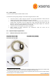
The RS‐422 MTi cable (CA‐USB6) is compatible with the RS‐422 version of the MTi. Blue cable markers are
locatedattheconnectorandthecasingforvisualdistinctionbetweentheRS‐232MTicable.TheMTxcannot
beorderedwithRS‐422interfacethereforenoRS‐422MTxcableisavailable.TheRS‐485MTi/MTxcablehas
yellowcablemarkerstoindicateRS‐485interfaceinsteadofRS‐232.
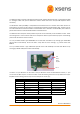
TheUSB‐serialdataandpowercableprovideseasyaccesstotheindividualpinsoftheMotionTracker.Inside
thehousingthereisafreeconnectorthatcanforexamplebeusedforsynchronizationpurposes.Thefollowing
photoshowsthelocationoftheconnector.
It is a 9‐pins Molex header type 53048‐0910 and it mates with the Molex crimp housing type 51021‐0900
(Farnell InOne code 615122). Farnell also offers crimp leads for these housings, e.g. Farnell InOne code
889570.
The 7 pins Molex header is type 53047‐0710 (Farnell InOne code 9732870) and mates with Molex crimp
housingtype51021‐0700(FarnellInOnecode615110).
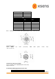
Thefirst5or7pindefinitionsarethesameasthepin definitionsoftheconnectedMotionTracker,i.e.pins
onetosevenforMTiandpinsonetofiveforMTx.Checkthefollowingsectionsforthepindefinitionsofyour
MTi/MTx.Pin8isalwaysgroundandpin9isreserved(donotusethispin).
Molexpin MTiRS‐232 MTiRS‐485 MTiRS‐422
Pin1 VCC VCC VCC
Pin2 GND GND GND
Pin3 AnalogIN Y/A TX+/A1(sensor)
Pin4 TX(sensor) Z/ B TX‐ /B1(sensor)
Pin5 RX(sensor) Reserved RX+/A2(sensor)
Pin6 SyncOut SyncOut RX‐ /B2(sensor)
Pin7 SyncIn SyncIn SyncIn
Molexpin MTxRS‐232 MTxRS‐485
Pin1 VCC VCC
Pin2 GND GND
Pin1
Vcc
Gnd
Gnd
SyncIn