
User manual


DocumentMT0100P.N
©XsensTechnologiesB.V. MTiandMTxUserManualandTechnicalDocumentation
20
2. AheadingresetthatredefinestheX‐axisoftheglobalcoordinateframewhilemaintainingtheZ‐axis
along the vertical (also known as “boresighting”). After the heading reset the orientation will be
expressedwithrespecttothenewglobal(earthfixed)referenceframe.
3. Anobjectresetthatdefineshowthesensorisorientedwithrespecttothecoordinateaxestowhichit
isattached.Aftertheobjectreset,boththeorientationandthecalibratedsensordataareexpressed
withrespecttotheaxesoftheobject.
4. Acombinedobject/headingreset,referredtoasalignment.
NOTE:Forallco‐ordinatesystemresetfunctionsitisimportanttorememberthatthehousingoftheMTxcan
not be considered an accurate reference. Placement and subsequent aligning must be done very carefully
otherwise(alignment)errorsmaybeinduced.
4.6.2 Arbitraryalignment
If the measured kinematics is required in an object coordinate system (O) with a known orientation with
respecttostandardsensorcoordinateframe(S),theobjectalignmentmatrixcanalsobesetwithanarbitrary
but known orientation. This can be useful if for mechanical reasons the MTi / MTx can only be fastened in
some specific orientation. The MTi and MTx Low‐level communication protocol describes the message
SetObjectAlignmentthatisrequiredtosetthematrix.
Theobjectalignmentmatrix(R
OS
)isappliedtotheoutputdata(R
GS
)accordingtothefollowingequations.For
3Dorientationdata,
()
T
RRR=
R=
S
ss
001
⎡⎤
GO GS OS
andforinertialandmagneticdata.
OSO
Example
Theobjectalignmentmatrixisgivenby
010
100
OS
R
⎢⎥
=
⎢⎥
⎢⎥
−
⎣⎦
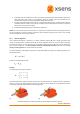
Here O represents the object coordinate system and S the standard sensor coordinate system described in
section2.1.1.OncetheobjectalignmentmatrixissettoR
OS
,thesensoroutputwillbeexpressedwithrespect
totheobjectcoordinatesystemdrawninfollowingfigure(b).
(a) (b)
TheMTiwiththesensorcoordinateframe(a)andtheobjectcoordinateframe(b).