
User manual


DocumentMT0100P.N
©XsensTechnologiesB.V. MTiandMTxUserManualandTechnicalDocumentation
18
11,1,1,
22,2,2,
33, 3, 3,
00
00
00
O
xyz
Txy
xyz
Gaaa
KGaaa
Ga a a
⎡⎤
⎡⎤
⎢⎥
⎢⎥
=+
⎢⎥
⎢⎥
⎢⎥
⎢⎥
⎣⎦
⎣⎦
z
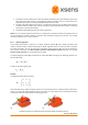
WithOrepresentinghigherordermodelsandtemperaturemodelling,g‐sensitivitycorrections,etc.
EachindividualMTiandMTxismodeledfortemperaturedependenceofbothgainandbiasforallsensorsand
other effects. This modeling is not represented in the simple model in the above equations, but is
implementedinthefirmware.
ThebasicindicativeparametersintheabovemodelofyourindividualMTiorMTxcanbefoundontheMTTest
andCalibrationCertificate.
4.5.2 Calibratedinertialand magneticdataoutputmode
Outputofcalibrated3Dlinearacceleration,3Drateofturn(gyro)and3Dmagneticfielddataisinsensor‐fixed
coordinatesystem(S).
Theunitsofthecalibrateddataoutputareasfollows:
Vector Unit
Acceleration m/s
2
Angularvelocity(rateofturn) rad/s
Magneticfield a.u.(arbitraryunits)normalizedtoearthfieldstrength
The calibrated data is “unprocessed”, i.e. only the physical calibration model is applied to the 16‐bit values
retrievedfromtheAD‐converters.Thereisnoadditionalfiltering,orothertemporalprocessingappliedtothe
data.Thebandwidthsofthesignalsareasstatedinthedatasheetandsection4.3.
The accelerometer / rate‐of‐turn / magnetometer data can be individually dis‐ or enabled. See
SetOutputSettingsmessageinsection5.3.3.
NOTE:Thelinear3Daccelerometersmeasureallaccelerations,includingtheaccelerationduetogravity.Thisis
inherenttoallaccelerometers.Therefore,ifyouwishtousethe3DlinearaccelerationsoutputbytheMTi/
MTxtoestimatethe“free”acceleration(i.e.2
nd
derivativeofposition)gravitymustfirstbesubtracted.
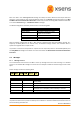
Theoutputdefinitionincalibrateddataoutputmodeis:
MTData DATA =
MID50(0x32)
All data elements in DATA field are FLOATS (4 bytes) , unless specified otherwise by modifying the
OutputSettingDataFormatfield.
magZmagYmagXgyrZgyrYgyrXaccZaccYaccX