
User manual


DocumentMT0100P.N
©XsensTechnologiesB.V. MTiandMTxUserManualandTechnicalDocumentation
10
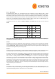
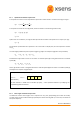
Highaccuracyalignment between the (plastic) housing and the sensor‐fixed output coordinate system (S) is
notpossiblefortheMTxforobviousreasons.TheactualalignmentbetweentheSco‐ordinatesystemandthe
bottompartoftheplastichousingisguaranteedto<3°.
Thenon‐orthogonalitybetweentheaxesofthebody‐fixedco‐ordinatesystem,S,is<0.1°.Thisalsomeansthat
theoutputof3Dlinearacceleration,3Drateofturn(gyro)and3Dmagneticfielddataallwillhaveorthogonal
XYZreadingswithin<0.1°asdefinedinfigure1.
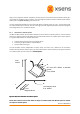
4.1.2 Orientationco‐ordinatesystem
TheMTiandMTxcalculatetheorientationbetweenthesensor‐fixedco‐ordinatesystem,S, andaearth‐fixed
referenceco‐ordinatesystem,G.Bydefaultthelocalearth‐fixedreferenceco‐ordinatesystemusedisdefined
asarighthandedCartesianco‐ordinatesystemwith:
• XpositivewhenpointingtothelocalmagneticNorth.
• Yaccordingtorighthandedco‐ordinates(West).
• Zpositivewhenpointingup.
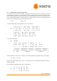
The 3D orientation output (independent of output mode, see section 4.3) is defined as the orientation
betweenthebody‐fixedco‐ordinatesystem,S,andtheearth‐fixedco‐ordinatesystem,G,usingtheearth‐fixed
co‐ordinatesystem,G,asthereferenceco‐ordinatesystem.ordinatesystem.
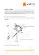
Figure3:MTintheearth‐fixedco‐ordinatesystemFigure3:MTintheearth‐fixedco‐ordinatesystem
Pleasereferto section 4.5forfurtherdetailsonoutputco‐ordinatesystemsanddifferentoptionstoredefine
theoutputco‐ordinatesystems.
Pleasereferto section 4.5forfurtherdetailsonoutputco‐ordinatesystemsanddifferentoptionstoredefine
theoutputco‐ordinatesystems.
Local
Magnetic North
Local
vertical
z
x
y
G
Local tangent plane
Z up, default
X
Z
Y
S
MTi and MTx default co-ordinate
system
Z up, default