
Service manual
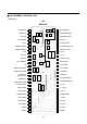


Pin
Name
Voltage and
Peripheral circuit of pins Description of function
No. wave Information
75
1.15k 375 2k
1.5k 1.5k
R
1.7k 3.2k
4.7k
200
5k
40k
20k
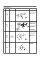
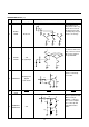
34
BLACK
About 3.2V
HOLD
35
KILLER 7.6V
FILTER at signal input
Normally 4.8V
36 CONTRAST Applied
from outside
37
GND-2
(VCD)
38
CHROMA IN/
4.5V
BRIGHTNESS
Pin holding the most
dark part of a video sig-
nal. As R is increased,
the black peak is held;
contrarily, the peak gets
cloaer to an average.
To decrease killer sensi-
tivity, connect a several
M of resistor between
the pin and GND.
Can be controlled by
5.1V center
Chroma signal standard.
Make an entry at
200mV
P
-
P
. This pin is
also used as a bright-
ness control pin. DC
reproduction ratio is
100%.
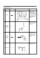
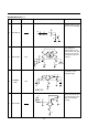
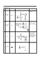
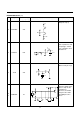
DESCRIPTION OF PIN (cont).
670
100
40k
20k
20k
33p
30p
4.5V