
Service manual


■ IY03 (LA7411)
1. Case Outline : DIP-24S (300mil) Plastic Package
2. Application : VHS format VTR Record and Playback Head Amplifiers
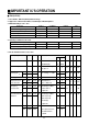
3. Maximum Ratings at Ta = 25°C
4. Operating conditions at Ta = 25°C
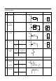
5. Electrical Characteristics at Ta = 25°C
43
■■
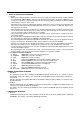
IMPORTANT IC'S OPERATION
Parameter Symbol Conditions Ratings Unit
Maximum supply voltage VCC max 7.0 V
Allowable power dissipation Pd max Ta ≦ 6.5°C 700 mW
Operating temperature Topg -10 to +65 °C
Storage temperature Tstg -40 to +150 °C
Parameter Symbol Conditions Ratings Unit
Recommended supply voltage VC 5.0 V
Operating supply voltage range VCC opg 4.80 to 5.50 V
Parameter Symbol
In- Out
Conditions min typ max Unit
-put -put
T1 T2
PB mode T12:5.0V T10:OPEN EP/ SW30
T4:OPEN (PB) SP MUTE
Current dissipation I CCP The current flowing
0141822mA
into pins 12
Voltage gain
L CH1 GVP 1 T17A T7A
Vi = 38mVpp. f = 1MHz
0
56.5 59.5 62.5 dB
H CH2 GVP 2 T20A 2.5
Voltage gain difference △GVP 1 GVP1-GVP2 -1 0 1 dB
Input conversion CH1 VNIN 1 T17A T7A VOUT/GVP1.2 0
1.1 1.5
µVrms
noise distortion CH2 VNIN2 T20A after 1.1MHz LPF 2.5
Frequency CH1 △V fp 1 T17A T7A Vi=38mVpp. f=7MHz 0
characteristics CH2 △Vfp 2 T20A V OUT/GVP1.2 2.5 -2.5 1 dB
output ratio
Second harmonic CH1 V HDP 1 T17A T7A Vi=38mVpp. f=4MHz 0 -40 -35 dB
distortion CH2 VHDP 2 T20A (8M component)/ 2.5
(4M component)
Vi=38mVpp
output ratio
Maximum output level
CH1 V OMP 1 T17A T7A f=1MHz 0 1.0 1.2 Vpp
CH2 V OMP 2 T20A The output level when 2.5
the third harmoinic
is-30dB.