
Service manual
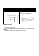

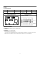
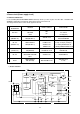

Location of Adjustment Parts Observation Waveform
MAIN PCB Horizontal Axis : S/DIV
Vertical Axis : CH1 : H/SW, CH2 : ENVELOPE
1. SERVO
1-1) X-path and P2, P3 Adjustment
Adjustment Procedure
1. Preparation
1) Set the AUTO TRACKING to OFF using REMOCON.
2) Play back the Test tape (Color Bar)
3) Set the oscilloscope to the CHOP mode. Connect CHI to the H/W (PY09) and CH2 to the ENVELOPE (PY09) and
trigger the scope with the signal from CH1.
2. Adjustment
1) Adjust CORN SCREW to position to maximize the width of the ENVELOPE pluse.
2) Adjust P2 to position which the edge of ENVELOPE signal has equal degree to the body of ENVELOPE signal.
Adjusting P3 is same to P2's.
3. Remark
1) After adjusting, press stop button to eject the tape.
2) Insert the tape into deck to confirm Autotracking.
3) If Normal screen is showed up as soon as it is start to play, adjustment becomes good.
If not, Adjust repeatedly to operate autotracking.
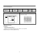
4) To know P2, P3, and CORN SCREW, refer from 'The schematic diagram of tape transporting system' on page 23
■■
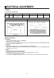
ELECTRICAL ADJUSTMENTS
29
Item Mode Adjustment parts Check point Test equipments Test tape Input signal
X-path PLAY CORN SCREW PY09 Oscilloscope DN-1
P2, P3
P2, P3
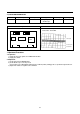
DECK A'S
MAIN PCB
PY09
PY05
Y/C
BOARD
⊕RN90