
Service manual

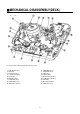


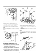

Cam Gear, and F/L Rack Removal (fig. 22)
1. Remove the cam gear ⑦ form the deck mechanism.
2. Remove the relay lever ⑥ from the main base ⑤.
3. Remove the F/L rack ⑧ from the deck mechanism.
NOTE :
When reassembling, align the assembly as shown in Fig.
23 & 24.
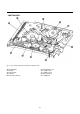
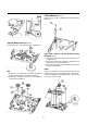
S/T Main & Sub Brakes Removal (Fig. 25)
1. Unhook the main brake spring ① from the T main brake
lever ③.
2. Disconnect the main brake lever assembly ② and T
main brake lever ③ from the main base ⑧.
3. Unhook the s sub brake spring ④ from the main base
and disconnect the s sub brake lever assembly ⑤ from
the main base ⑧.
4. Unlook the T sub brake spring ⑥ from the main base
and disconnect the T sub brake lever assembly ⑦ from
the main base ⑧.
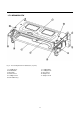
Tension Band Assembly Removal (Fig. 26, 27)
1. Remove the tension spring ② from the main base ①
(Fig. 26)
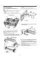
2. Turn the deck mechanism upside down (fig. 27) is facing
down (fig. 27)
NOTE :
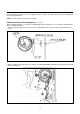
• After reassembling, adjust the position of the tension pole
as shown in fig. 28.
• Avoid getting grease or oil on the felt section of the band
brake.
15
Fig. 23- L/C Bracket Assembly Alignment
Fig. 25- Main Plate Removal
Fig. 26- Tension Band Assembly Removal (1)
Fig. 24- Cam Gear/F/L Rack Alignment