
Service manual

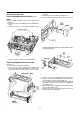


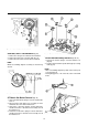

A/C Head Assembly Removal (Fig. 21)
1. Remove one (1) nut hex from the A/C head assembly ①
(Fig. 21)
2. Remove the A/C head assembly ② and remove the A/C
head spring ③ from the A/C head assembly ②.
NOTE :
After reinstalling, perform all A/CHead adjustment proce-
dures and all tape path alignment procedures in publication.
Perform the "Audio Bias Level Adjustment" in the "Electrical
Adjustment" section of this service manual.
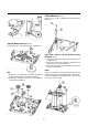
L/C Bracket Assembly removal (Fig. 22)
1. Remove one (1) screw ① from the L/C bracket assem-
bly ②and remove the L/C bracket assembly ② from the
deck mechanism (Fig. 22)
NOTE :
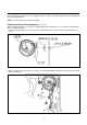
When reassembling, refer to Fig. 23 for alignment instruc-
tions.
Replacement of Pinch Lever Total Assembly
Removal
(Fig. 22)
1. Remove one (1) washer ③.
2. Unhook the pinch spring ④ from the main base ⑤ and
remove the pinch lever total assembly ⑥.
NOTE :
Take care not to get oil on the outside surface of the pinch
roller ⑩.
14
Fig. 20- Loading Gears/Loading Rack Alignment
Fig. 21- A/C Head Assembly Removal
Fig. 22- Replacement of L/C Bracket Total Assembly/Pinch
Lever Total Assembly/cam Gear/Relay Lever/F/L Rack
⑩