
Service manual


■■
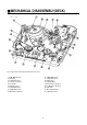
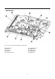
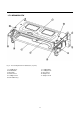
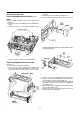
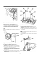
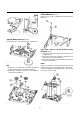
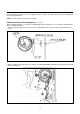
MECHANICAL DISASSEMBLY(DECK)
9
1. Earth Bracket Ass'y
2. FE Head
3. S-Slant Pole Ass'y
4. Tension Lever Ass'y
5. Reel Table
6. Main Base Ass'y
7. S-Sub Brake Ass'y
8. S-Main Brake Ass'y
9. Idler Plate Total Ass'y
10.T-Main Brake Ass'y
11.T-Sub Brake Ass'y
12.Relay Lever
13.Capstan Motor
14.Pinch Lever Total Ass'y
15.L/C Bracker Total Ass'y
16.Cam Gear
17.AC Head Total Ass'y
18.T-Slant Pole Ass'y
Fig. 9- tape Transport Mechanism Identification (Top View)
1.TOP VIEW