
Service manual


F. PLAYBACK PHASE ADJUSTMENT(Fig. 5.6)
Test Points: PT01 PIN # Main
Video Out Jack Rear Panel
Adjust: REC SWITCH Main
The Pulse Generator (PG) Shifter determines the video
head switching point during playback. Misadjustment of
the PG Shifter may cause head switching noise in the
picture and/or vertical jitter.
1. Load the instrument with an alignment tape and play
back the color bar signal or monoscope signal.
2. Connect Path Fixture to PT01.
3. Connect channel-1 scope probe (1V/div.:
50µsec/div.) to PT01 PIN #. Trigger the scope on
channel-1.
4. Connect channel-2 scope probe (1V/div.) to the
Video Out Jack.
5. Set the scope to (-) slope and press the REC SW, the
alignment is performed automatically. Confirm that
the trailing edge of the SW 30Hz pulse is placed
6.5H±0.5H (horizontal) lines before the start of
vertical sync pulse.
G. Adjustment of the LINEARITY(Fig. 5.7)
a. Connect the PT01 on the MAIN CIRCUIT BOARD
with a PATH ADJ.FIXTURE.
b. Play back an ALIGNMENT TAPE (DP2 : STAIR
STEP).
c. Connect the FIXTURE S/W PULSE TEST PIN on
the PATH ADJ. CHANNEL-1 SCOPE PROBE.
d. Connect the VIDEO OUT on the MAIN CIRCUIT
BOARD
with a CHANNEL-2 SCOPE PROBE.(1V/div).
e. Adjust the VR CONTROL on the ADJ. FIXTURE
until the ENVELOPE signal is maximum while play
back the ALIGNMENET TAPE.
f. Adjust the S/T GUIDE ROLLER until the envelope
signal waveforms of the entrance and exit sides are as
shown in Fig. 5-7.
22
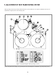
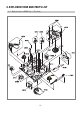
FIg.5.5 Adjustment of the X-POSITION
S/W PULSE TEST PIN PATH ADJ. FIXTURE
ENVELOPE TEST PIN PATH ADJ.FIXTURE
Measurement Equipment OSILLOSCOPE
VR CONTROL PATH ADJ.FIXTURE
S/T GUIDE ROLLER TAPE TRANSPORT SECTION
Test Point
Adjustment
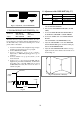
FIg.5.7 Adjustment of Linearity
SWITCHING
SW30Hz
PULSE
VIDEO
OUTPUT
V. SYNC
6.5H–0.5
Fig.5.6