
Service manual

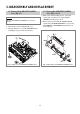


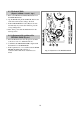
3-6. Disassembly of the LC BRKT ASS’Y,
PINCH LEVER TOTAL ASS’Y (Fig. 3.9)
a. Separate the LC BRKT Ass’y @ after removing 3
screws !.
b. Separate the LC BRKT Ass’y @ from the DECK
MECHANISM.
c. Remove the PINCH LEVER TOTAL Ass’y #.
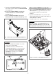
3-7. Disassembly of the CAM GEAR,
RELAY LEVER, FL RACK (Fig. 3.9)
a. Separate the CAM GEAR % from the MAINBASE.
b. Separate the RELAY LEVER ^ from the
MAINBASE.
c. Separate the FL RACK & from MAINBASE by
moving to the arrow direction.
CAUTION:
• After the assembly of the PINCH LEVER TOTAL
Ass’y, adjust the tape transmission section by
refering to chapter 5.
• Be careful not to get grease or other foreign
materials on the surface of the pinch roller $.
• Make sure if the end of the PINCH SPRING
PINCH “A” is located at the end of the slot of CAM
GEAR “B” in assembly. (Refer to Fig. 4.3)
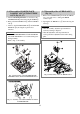
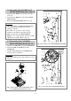
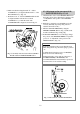
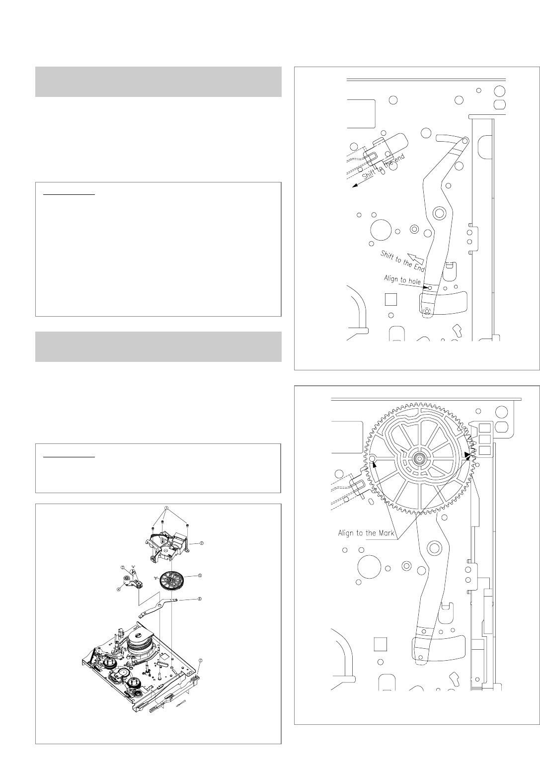
CAUTION:
• When reassembling, refer to Fig. 3.10, Fig. 3.11 and
chapter 4.
FIg. 3.9 Disassembly of the LC BRACKET ASS’Y
from the PINCH LEVER TOTAL ASS’Y
FIg. 3.10 Assembly of the CAM GEAR, RELAY LEVER
FIg. 3.11 Assembly of the CAM GEAR, FL RACK
14