
Service manual

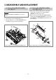


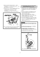
3-4. Disassembly of LOADING RACK,
LOADING ASS’Y, S/T SLANT POLE
ASS’Y (Fig. 3.6, 3.7)
a.
Turn the DECK MECHANISM over and remove the
LOADING RACK@ after unscrewing the SCREW !.
b. Remove the R LOADING AS # and L LOADING
AS $.
c. Remove the S SLANT POLE AS % and T SLANT
POLE AS ^ by moving those part in arrow
direction.
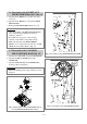
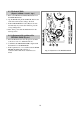
3-5. Disassembly of the A/C HEAD ASS’Y
(Fig. 3.8)
a. Remove the CONNECTOR @ from the AC HEAD
Ass’y, use caution not to damage the HEAD
connector pins.
b. Separate the AC HEAD Ass’y ! after removing the
screw #.
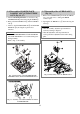
CAUTION:
• Take care GUIDE ROLLER of S/T SLANT POLE
AS and SLANT POLE not to be stained with grease
during assembly.
• Refer to Fig. 3.7 in assembly.
FIg. 3.6 Disassembly of the LOADING RACK,
LOADING ASS’Y and the SLANT POLE ASS’Y
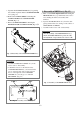
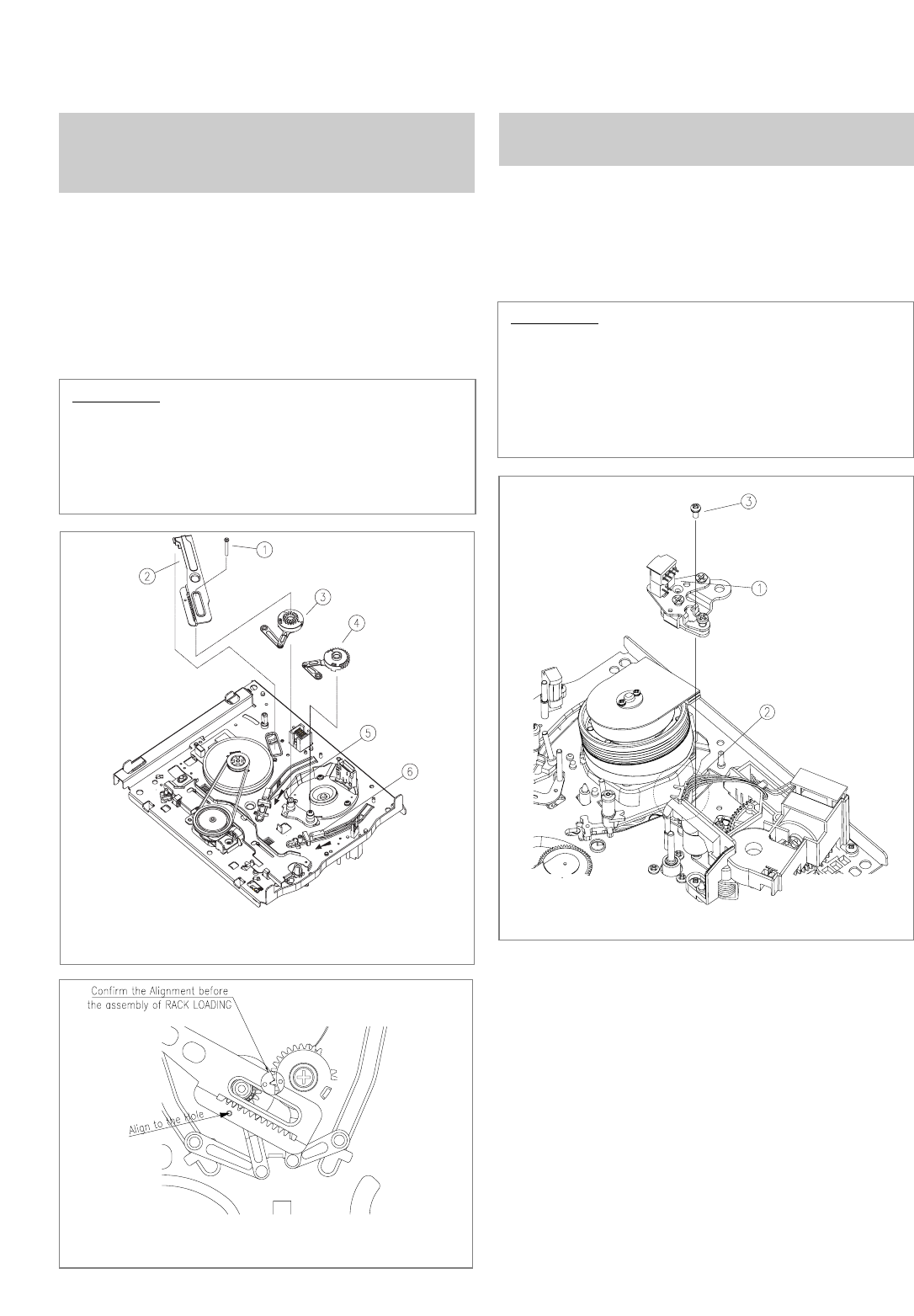
FIg. 3.7 Assembly of the L/R LOADING AS and the
LOADING RACK
CAUTION:
• After the assembly, adjust the tape transmission
section by refering to chapter 5.
• After the adjustment of the tape transmission
section, paint the 3 adjustment screw with locking
paint.
FIg. 3.8 Disassembly of the AC HEAD ASS’Y
13