S/M No. : C1B0K0S002 Service Manual Microwave Oven Model : KOC-1B0K0S ✔ Caution : In this Manual, some parts can be changed for improving, their performance without notice in the parts list. So, if you need the latest parts information,please refer to PPL(Parts Price List) in Service Information Center (http://svc.dwe.co.kr). DAEWOO ELECTRONICS CO., LTD. http : //svc.dwe.co.kr Nov.
PRECAUTIONS TO BE OBSERVED BEFORE AND DURING SERVICING TO AVOID POSSIBLE EXPOSURE TO EXCESSIVE MICROWAVE ENERGY (a) Do not operate or allow the oven to be operated with the door open.
1. SAFETY AND PRECAUTIONS 1. For Safe Operation Damage that allows the microwave energy (that cooks or heats the food) to escape will result in poor cooking and may cause serious bodily injury to the operator. IF ANY OF THE FOLLOWING CONDITIONS EXIST, OPERATOR MUST NOT USE THE APPLIANCE. (Only a trained service personnel should make repairs.) 1) A broken door hinge. 2) A broken door viewing screen. 3) A broken front panel, oven cavity. 4) A loosened door lock. 5) A broken door lock.
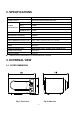
2. SPECIFICATIONS MODEL KOC-1B0K POWER SUPPLY 230V~50Hz, SINGLE PHASE WITH EARTHING MICROWAVE 1500W POWER GRILL 1600W CONSUMPTION CONVECTION 2300W COMBINATION 3100W MICROWAVE ENERGY OUTPUT 1000W (IEC705) MICROWAVE FREQUENCY 2450MHz OUTSIDE DIMENSIONS (W X H X D) 560 x 344 x 542 mm (22.0 x 13.5 x 21.3 in.) l CAVITY DIMENSIONS (W X H X D) 368.5 x 246 x 376.5 mm (14.5 x 9.7 x 14.8 in.) NET WEIGHT APPROX. 21.5 Kg ( 47.6 lbs.
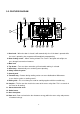
3-2. FEATURE DIAGRAM 1. Door hook – When the door is closed, it will automatically shut. If the door is opened while the oven is operating, the magnetron will immediately stop operating. 2. Door viewing screen – Allows viewing of food. The screen is designed so that light can pass through, but not the microwave. 3. Metal rack 4. Top heater – Turns on when convection, grill and combi cooking is selected. 5. Oven lamp – Automatically turns on during oven operating. 6. Safety interlock system 7.
4. INSTALLATION 1. Steady, flat location This microwave oven should be set on a steady, flat surface. This microwave oven is designed for counter top use only. 2. Leave space behind and side All air vents should be kept a clearance. If all vents are covered during operation, the oven may overheat and, eventually, cause failure. 3. Away from radio and TV sets Poor television reception and radio interference may result if the oven is located close to a TV, radio, antenna or feeder and so on.
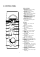
5. CONTROL PANEL DISPLAY WINDOW 1 2 3 4 7 6 5 language 1. MICROWAVE indicator, showing microwaving in progress. 2. DEFROST indicator, showing defrosting in progress. 3. GRILL (upper grill heater) indicator, showing grilling in progress. 4. GRILL (lower grill heater) indicator, showing grilling in progress. 5. CONVECTION indicator, showing convectioning in progress. 6. CHILD LOCK indicator. 7. % percentage microwave power level indicator.
6. DISASSEMBLY AND ASSEMBLY - Cautions to be observed when trouble shooting. Unlike many other appliances, the microwave oven is high-voltage, high-current equipment. It is completely safety during normal operation. However, carelessness in servicing the oven can result in an electric shock or possible danger from a short circuit. You are asked to observe the following precautions carefully. 1. Always remove the power plug from the outlet before servicing. 2.
✔ Caution: In this Service Manual, some parts can be changed for improving, their performance without notice in the parts list. So, if you need the latest parts information, please refer to PPL(Parts Price List) in Service information Center(http://svc.dwe.co.kr) 1. To remove cabinet (1) Remove four screws on cabinet back. (2) Push the cabinet backward. 2. To remove door assembly (1) Remove two screws which secure the stopper hinge top. (2) Remove the door assembly from top plate of cavity.
(1) Remove the gasket door from door plate. (2) Remove a screw from door plate. (3) Remove the door frame from door plate. (4) Remove the stopper hinge top from door plate. (5) Remove the spring and the hook. (6) Remove two screws from door frame. (7) Remove the handle door and barrier screen outer from door frame. (8) Remove the barrier screen outer from handle door. (9) Reverse the above steps for reassembly. 4. Method to reduce the gap between the door seal and the oven front surface.
✔ Caution: In this Service Manual, some parts can be changed for improving, their performance without notice in the parts list. So, if you need the latest parts information, please refer to PPL(Parts Price List) in Service information Center(http://svc.dwe.co.kr) 5. To remove control panel parts. REF.
6. To remove high voltage capacitor. (1) Remove a screw which secure the grounding ring terminal of the H.V.diode and the capacitor holder. (2) Remove the H.V. diode from the capacitor holder. (3) Reverse the above steps for reassembly. l High voltage circuit wiring 7. To remove magnetron. (1) Remove a screw which secure the magnetron. (2) Remove the magnetron. (3) Reverse the above steps for reassembly.
8. To remove wind guide assembly. (1) Remove a screw for earthing. (2) Remove the noise filter from the wind guide. (3) Remove a screw which secure the wind guide assembly. (4) Draw forward the wind guide assembly. (5) Pull the fan from the motor shaft. (6) Remove two screws which secure the motor shaded pole. (7) Remove the motor shaded pole. (8) Reverse the above steps for reassembly. 9. To remove H.V.transformer. (1) Remove four screws holding the H.V transformer. (2) Remove the H.V.transformer.
✔ Caution: In this Service Manual, some parts can be changed for improving, their performance without notice in the parts list. So, if you need the latest parts information, please refer to PPL(Parts Price List) in Service information Center(http://svc.dwe.co.kr) 10. To remove Lamp assembly parts. 1 6 7 2 8 3 5 4 9 REF.
✔ Caution: In this Service Manual, some parts can be changed for improving, their performance without notice in the parts list. So, if you need the latest parts information, please refer to PPL(Parts Price List) in Service information Center(http://svc.dwe.co.kr) 11. To remove Top heater assembly parts. 5 6 7 1 2 8 3 4 REF.
✔ Caution: In this Service Manual, some parts can be changed for improving, their performance without notice in the parts list. So, if you need the latest parts information, please refer to PPL(Parts Price List) in Service information Center(http://svc.dwe.co.kr) 12. To remove Rear heater assembly parts. 1 2 16 14 17 18 15 13 12 3 4 5 11 10 9 8 7 6 REF.
✔ Caution: In this Service Manual, some parts can be changed for improving, their performance without notice in the parts list. So, if you need the latest parts information, please refer to PPL(Parts Price List) in Service information Center(http://svc.dwe.co.kr) 13. To remove Motor synchro. And Under heater assembly parts. 5 4 3 2 1 CUTTING (6EA) REF.
7. INTERLOCK MECHANISM AND ADJUSTMENT The door lock mechanism is a device which has been specially designed to completely eliminate microwave radiation when the door is opened during operation, and thus to perfectly prevent the danger resulting from the leakage of microwave. (1) Primary interlock switch When the door is closed, the hook locks the oven door. If the door is not closed properly, the oven will not operate. When the door is losed, the hook pushes the lock lever downward.
8. TROUBLE SHOOTING GUIDE Following the procedures below to check if the oven is defective or not. 1. Check grounding before checking trouble. 2. Be careful of the high voltage circuit. 3. Discharge the high voltage capacitor. 4. When checking the continuity of the switches, fuse or high voltage transformer, disconnect one lead wire from these parts and then check continuity with the AC plug removed. To do otherwise may result in a false reading or damage to your meter.
. CONDITION Outlet has Proper voltage Fuse does not blow? CHECK RESULT CAUSE REMEDY Check continuity of magnetron No Continuity Defective magnetron. Replace Check continuity of noise filter board No Continuity Defective Noise filter board Replace Check continuity of Power supply cord No Continuity Open power supply cord Adjust Defective touch control Circuit Adjust Continuity NOTE : All these switches must be replaced at the same time, please refer to (7.
TROUBLE 3) Display shows all figures selected, but oven does not start cooking, even though desired program and time are set and start button is tapped . CONDITION Turn table motor and oven lamp do not turn on CHECK RESULT CAUSE REMEDY Check continuity of Primary interlock switch No Continuity malfunction of primary interlock switch Adjust or Replace Check continuity of Secondary interlock and D.O.M switch No Continuity Malfunction Of secondary Interlock and D.O.
TROUBLE 5) Bottom heater is not heated; food will not become hot. CONDITION Bottom heater is not heated. CHECK Check continuity of Primary interlock switch Check continuity of secondary interlock switch Check continuity of heater RESULT CAUSE REMEDY No Continuity Malfunction Of primary Interlock switch Adjust or Replace No Continuity Malfunction Of secondary interlock switch Adjust or replace No continuity Defective heater Check D.C voltage Being supplied to RELAY (RY7) coil 0V Approx.
TROUBLE 7) When “ERROR 2 & ERROR 3” come on display.
9. MEASUREMENT AND TEST 9-1. MEASUREMENT OF THE MICROWAVE POWER OUTPUT Microwave output power can be checked by indirectly measuring the temperature rise of a certain amount of water exposed to the microwave as directed below. PROCEDURE 1. 2. 3. 4. 5. 6. 7. Microwave power output measurement is made wit the microwave oven supplied at rated voltage and operated at its maximum microwave power setting with a load of 1000 ± 5cc of potable water.
9-2. MICROWAVE RADIATION TEST WARNING l l l l l Make sure to check the microwave leakage before and after repair of adjustment. Always start measuring of an unknown field to assure safety for operating personnel from microwave energy. Do not place your hands into any suspected microwave radiation field unless the safe density level is known. Care should be taken not to place the eyes in direct line with the source of microwave energy.
9-3. COMPONENT TEST PROCEDURE • • • High voltage is present at the high voltage terminal of the high voltage transformer during any cooking cycle. It is neither necessary nor advisable to attempt measurement of the high voltage. Before touching any oven components or wiring, always unplug the oven from its power source and discharge the capacitor. 1. High voltage transformer (A) Remove connections from the transformer terminals and check continuity.
9-4.
10.
F79 F78 F77 F76 F75 28 A00 F20 F74 B00 F21 F72 F01 F22 F71 F02 F73 F03 F18 F70 F19 F04 F69 F05 F68 F14 F80 F17 F23 F59 F67 F15 F16 F26 F06 F65 F11 F29 F27 F07 F10 F30 F64 F49 F28 F25 F57 F61 F09 F12 F58 F60 F13 F24 F53 F66 F08 F32 F35 F36 F33 F50 F31 F51 F34 F52 F53 F37 F42 F38 F56 F55 F54 F62 F44 F39 F40 F45 F41 F81 F46 F43 F47 F48 11. EXPLODED VIEW AND PARTS LIST 11-1. DOOR ASSEMBLY Refer to 6.Disassembly and assembly.
✔ Caution: In this Service Manual, some parts can be changed for improving, their performance without notice in the parts list. So, if you need the latest parts information, please refer to PPL(Parts Price List) in Service information Center(http://svc.dwe.co.
✔ Caution: In this Service Manual, some parts can be changed for improving, their performance without notice in the parts list. So, if you need the latest parts information, please refer to PPL(Parts Price List) in Service information Center(http://svc.dwe.co.kr) NO PART CORD PART NAME F36 3512766800 HARNESS CONVECTION-A KOC-1B0K0S 1 F37 3511407700 COVER HEATER *B SA1D T0.5 1 F38 3513302900 INSULATOR HEATER *B SA1D T0.
✔ Caution: In this Service Manual, some parts can be changed for improving, their performance without notice in the parts list. So, if you need the latest parts information, please refer to PPL(Parts Price List) in Service information Center(http://svc.dwe.co.
12. PRINTED CIRCUIT BOARD 1. CIRCUIT CHECK PROCEDURE 1) Low voltage transformer check The low voltage transformer is located on the P.C.B. Measuring condition: Input voltage: 230 V / Frequency: 50Hz Terminal Voltage(load) Voltage(no load) 6 ¦ ¡ 7 AC 17.0V AC 19.9V 8 ¦ ¡ 9 AC 1.3V AC 1.6V 9 ¦ ¡ 10 AC 1.3V AC 1.6V NOTE1: Secondary side voltage of the low voltage transformer changes in proportion to fluctuation of power source voltage.
3) Case of no microwave oscillation (1) When touching M/W button, oven lamp turns on and Fan motor and turntable rotate, and cook indicator in display comes on. * Cause: RELAY 1 does not operate. - Check method STATE RELAY 1 ON RELAY 1 OFF POINT A +5V DC GND POINT B GND +24V DC (2) When touching M/W button, oven lamp does not turn on and turntable motor does not rotate but cook indicator in display comes on. * Cause: RELAY 4 does not operate.
4) Case of no heating of upper grill When touching GRILL1 & COMBI button, oven lamp turns on and fan motor and turntable motor rotate and cook indicator in the display comes on. l Cause: RELAY 2 does not operate. STATE RELAY 2 ON RELAY 2 OFF 5) Case of no heating of POINT A +5V DC GND POINT B GND +24V DC lower grill When touching GRILL2 & COMBI button, oven lamp turns on and fan motor and turntable motor rotate and cook indicator in the display comes on. l Cause: RELAY 7 does not operate.
STATE RELAY 3 ON RELAY 3 OFF POINT A +5V DC GND 7) Case of no stopping of the count do POINT B GND +24V DC wn timer When the door is opened during operation, the count down timer does not stop. B A - Check method A B STATE 1) DOOR OPEN OPEN +5V DC 2) DOOR CLOSED CLOSE GND POINT CHECK NO METHOD REMEDY 1 Check the stage(ON,OFF) of the door open monitor switch by resistance measurement. 35 Replace door open monitor switch.
13. P.C.B.
✔ Caution: In this Service Manual, some parts can be changed for improving, their performance without notice in the parts list. So, if you need the latest parts information, please refer to PPL(Parts Price List) in Service information Center(http://svc.dwe.co.