
Installation guide


Installation
Specifications
e e
27°/30"/36"
Dacor
__
ona
+
|
single
wall
oven
~«—
3/4"
Min.
ele
@||
warming
ele
|
tf
(tgmm)
=
36"
T
drawer
S
+
yp.
—~+D
Warming
120
Vac~
C
(914
mm)
Warming
120
Vac
t
drawer
elect.
|
drawer
electrical
Cc
1
outlet
Vay
Min.*
_D
L__e@
id
;
f
(19
mm)
Warming
120
Vac-—
drawer
elect.
rT
4
|e
A
|
=)
1
1/2"
(38
mm)
—]
Cooktop
a
lpical
countertop
Toe
kick 3/4"
Min.*
A
—==<—
3/4”
Min*
|
A
|
(19
mm)
e
Warming
gb
19mm)
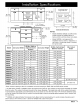
Cutouts
Dimensions
@
drawer
1
°
a
NOTES:
e
*
Models
EWD36,
OWD24
and
IWD
series
36"
Typ.
120
Vac
models
cannot
be
installed
above
or
(914
mm)
+—
a
—+|
stecttical
below
another
warming
drawer
(any
type).
e
B
*
Model
OWD24
is
not
approved
for
installation
above,
below
or
adjacent
to
a
wall
oven
or
a
warming
drawer,
including
Y
the
same
model.
(B)
Min.
Width
to
. . .
Model
|
(A)
Cutout
Width
|
Adjacent
Doors/
|
(C)
Cutout
Height
|
(2)
Min.
Vertical
Gap
|
—
Min.
Cutout
Between
Cutouts
Depth
Drawers
ERWD30
|
28
1/2”
(724
mm)
|
30
1/4”
(768
mm)*
9
1/8”
(232
mm)
1
1/4”
(32
mm)*
EWD24
22
1/2”
(572
mm)
|
24
1/4”
(616
mm)*
9
1/8”
(232
mm)
1
1/4”
(32
mm)*
EWD27
25
1/2”
(648
mm)
|
27
1/4”
(692
mm)*
9
1/8”
(232
mm)
1
1/4”
(32
mm)*
EWD30
28
1/2”
(724
mm)
|
30
1/4”
(768
mm)*
9
1/8”
(232
mm)
1
1/4”
(32
mm)*
EWD36
34
1/2”
(876
mm)
|
36
1/4”
(921
mm)*
9
1/8”
(232
mm)
NA
IWD24
22
1/2”
(572
mm)
“ee
9
1/8”
(232
mm)
NA
IWD27
25
1/2”
(648
mm)
“ee
9
1/8”
(232
mm)
NA
24”
(610
mm)
IWD30
28
1/2”
(724
mm)
“ee
9
1/8”
(232
mm)
NA
MRWD27
|
25
1/2”
(648
mm)
27”
(686
mm)*
9
1/8”
(232
mm)
1
1/4”
(32
mm)*
MRWD30
|
28
1/2”
(724
mm)
30”
(762
mm)*
9
1/8”
(232
mm)
1
1/4”
(32
mm)*
MWDH27
|
25
1/2”
(648
mm)
|
27
1/4”
(692
mm)*
9
1/8”
(232
mm)
1
1/4”
(32
mm)*
MWDH30
|
28
1/2”
(724
mm)
|
30
1/4”
(768
mm)*
9
1/8”
(232
mm)
1
1/4”
(32
mm)*
MWDV27
|
25
1/2”
(648
mm)
|
27
1/4”
(692
mm)*
9
1/8”
(232
mm)
1
1/4”
(32
mm)*
MWDV30
|
28
1/2”
(724
mm)
|
30
1/4”
(768
mm)*
9
1/8”
(232
mm)
1
1/4”
(32
mm)*
OWD24_
|
22
5/8”
(575
mm)
|
24
1/4”
(616
mm)***
|
11
15/16”
(303
mm)
NA
20
1/8”
(511
mm)
PWD27
25
1/2”
(648
mm)
|
27
1/4”
(692
mm)*
9
1/8”
(232
mm)
1
1/4”
(32
mm)*
24"
(610
mm)
PWD30
28
1/2”
(724
mm)
|
30
1/4”
(768
mm)*
9
1/8”
(232
mm)
1
1/4”
(32
mm)*
*
Bare
minimum
spacing
to
allow
for
ventilation
and
avoid
scraping
on
EWD,
MW
and
PWD
series
models.
**
On
IWD
series
models
or
OWD24
without
the
optional
front
panel
kit:
The
chassis
and
the
drawer
faceplate
are
smaller
than
the
cutout.
The
custom
front
panel
mounts
to
the
drawer
faceplate.
The
height
and
width
of
the
custom
front
panel
must
exceed
the
appropriate
cutout
dimensions
(A
and
C
above)
to
cover
the
hole.
Allow
1/4"
minimum
additional
space
on
the
top,
bottom
and
sides
from
the
custom
front
panel
edge
to
prevent
scraping
against
adjacent
doors,
drawers
and
the
countertop.
**
OWD24
with
optional
factory
front
panel
kit
only.
Bare
minimum
spacing
shown
to
avoid
scraping.
Gap
above
and
below
cutout
is
3/4”
minimum.
See
**
above
for
OWD24
with
custom
front
panel.
dacor
5