
Installation guide


7
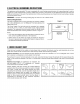
VENTILATION
SYSTEM
(PREPARING
OVEN
FOR
INSTALLATION)
This
Microwave
Oven/Hood
is
designed
for
adaptation
to
three
types
of
hood
ventilation
systems.
Select
the
type
required
for
your
installation.
Vertical
Exhaust
—
outside
ventilation.
Follow
installation
procedure
(A).
Horizontal
Exhaust
—
outside
ventilation.
Follow
installation
procedure
(B).
Recirculating
—
non-vented,
ductless.
Follow
installation
procedure
(C).
Recirculating
requires
the
use
of
the
Charcoal
Filter.
Exhaust
Damper
Assembly
5
Figure
5
(A)
VERTICAL
EXHAUST:
OUTSIDE
VENTILATION
The
unit
is
shipped
assembled
for
vertical
exhaust.
Attach
the
Exhaust
Damper
Assembly
to
the
fan
cover
on
the
top
of
the
outercase
cabinet
by
sliding
it
into
the
slits
in
the
same
direction
as
the
arrow
mark.
Using
Tapping
Screw
4x12
from
the
INSTALLATION
HARDWARE,
tighten
into
place.
See
Fig
5.
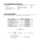
(B)
HORIZONTAL
EXHAUST:
OUTSIDE
VENTILATION
1.
Remove
and
save
6
screws.
Remove
fan
cover
bracket
as
shown
in
Fig
6.
2.
Withdrawn
hood
fan
unit
carefully
and
slip
wires
out
of
wire
box.
Rotate
hood
fan
unit
90°
so
that
exhaust
ports
are
facing
rear
of
oven
unit.
See
Fig
7.
CAUTION:
Do
not
pull
or
stretch
hood
fan
wiring.
3.
Replace
hood
fan
unit
into
the
oven
unit.
Be
careful
not
to
pinch
the
lead
wire
between
the
inner
bracket
and
the
hood
fan
unit.
See
Fig
8.
4.
Put
the
lead
wire
into
wire
box.
5.
Replace
the
fan
cover
bracket.
Make
sure
the
fan
blades
are
visible
through
the
rear
openings
in
the
oven
before
proceeding.
Aitach
fan
cover
bracket
to
unit
with
6
screws.
See
Fig
9.
The
hood
fan
unit
is
now
rotated
for
horizontal
exhaust
operation.
6.
Attach
the
Exhaust
Damper
Assembly
to
the
back
of
the
mounting
plate
by
sliding
it
into
the
slits
in
the
same
direction
as
the
arrow.
See
Fig
10.
Using
Tapping
Screw
4x12
from
the
INSTALLATION
HARDWARE,
tighten
into
place.
Figure
6
Figure
7
Fan
cover
bracket