D.W.
How to Contact us: Telephone: 610-793-2526 Fax: 610-793-1479 Mail: P.O. Box 57, Pocopson, PA 19366 U.S.A. Shipping Address: 182 Bragg Hill Road West Chester, PA 19382 U.S.A. e-mail: dwfearn@dwfearn.com www.dwfearn.com D.W.
D.W. FEARN www.dwfearn.com H AND - CRAFTED PROFESSIONAL RECORDING EQUIPMENT P.O. Box 57 Pocopson, PA 19366 U.S.A. Tel: 610-793-2526 Fax: 610-793-1479 Certificate of RoHS Compliance D.W. Fearn is committed to manufacturing products that are fully-compliant with the EU RoHS Directive.
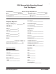
VT-15 Vacuum Tube Recording Channel Final Test Report Serial Number_______________ Mains Voltage 120/240 set to __________________ Date ________________ Tested by ________ VU Calibrated to _______________ dBm Test Equipment ____________________________ Microphone ________________________ Frequency Response: Line Input __________________ 20 cps to 20 kc/s +/- ___________ dB Instrument Input ____________ THD+Noise: C->E Switching ______________ 20 cps ______________ % Compressor: 200 cps _________
7 Table of Contents RoHS Compliance Data ..................................................................3 Final Test Report ............................................................................5 Warranty ........................................................................................9 History of the VT-15 .....................................................................11 1. Specifications ..........................................................................13 2. Description.....
8 D.W. Fearn shall not be liable for technical or editorial errors or omissions in this manual, nor for incidental or consequential damages resulting from the use of this material. This instruction manual contains information protected by copyright. No part of this manual may be photocopied or reproduced in any form without prior written consent from D.W. Fearn. Copyright ©2007 D.W. Fearn & Associates D.W.
9 Limited 5-Year Warranty During the warranty period, D.W. Fearn will, at no additional charge, repair or replace defective parts with new parts. This warranty does not extend to any VT-15 that has been damaged or rendered defective as a result of accident, misuse, or abuse; by the use of parts not manufactured or supplied by D.W. Fearn; or by unauthorized modification of the VT-15. Vacuum tubes are excepted from the 5-year warranty, but are warranted for 90 days from date of purchase.
11 History of the VT-15 Vacuum Tube Recording Channel With the success of the VT-1/VT-2 Vacuum Tube Microphone Preamplifiers, the VT4 LC Equalizer, the VT-7 Stereo Compressor, and the VT-I/F and VT-3 Vacuum Tube DIs, there was a great temptation to combine the features of all of these products into one recording channel. But I had a problem with the concept.
12 D.W.
13 1. S P E C I F I C AT I O N S Mic Input 150 ohms Input Load Impedance 1.5k ohms Minimum Input Level -65 dBm nominal Maximum Input Level @ 20 cps -30 dBm without pad -5 dBm with 20 dB pad Instrument Input impedance 1 Megohm Line Input Load Impedance 40k ohms Maximum Line Input Level @ 20 cps +25dBm (+35dBm with pad) Gain Frequency Response <60 dB optimum (capable of 75dB) ± 0.25 dB 20 cps to 20 kc ± 0.5 dB 11 cps to 28 kc -3 dB @ 0.5 cps & 50 kc THD + Noise <0.
14 1. S P E C I F I C AT I O N S (CONT’D) Compression Range up to 30dB Compression method Pulse-width modulator Equalizer: Low-frequency Boost Low-frequency Cut High-frequency Boost High-frequency Q High-frequency Cut 12 kc, shelving Power Requirements 100 cps, shelving 80 cps, shelving 9.8 kc, peaking 0.6 to 1.7 100, 120, or 220 VAC 50/60Hz, 50 W Dimensions 19” (48.26cm) W 5.25” (13.34cm) H 9” (22.86cm) D (VT-2 13” 22.9cm) Weight 18 lbs (8.
15 2. DESCRIPTION The D.W. Fearn VT-15 utilizes circuitry developed for the VT-1/VT-2 Vacuum Tube Microphone Preamplifiers, the VT-7 Stereo Compressor, and the VT-4 LC Equalizer. The Model VT-15 Recording Channel is designed to provide recording professionals with a sonically superior input device. It is typically used in sound recording studios for recording individual tracks.
16 D.W.
17 3. I N S TA L L AT I O N The VT-15 is carefully packed for shipment and it should survive all but the most brutal handling. If there is any damage, keep the shipping material for use during any possible claim for damage with the shipper. Included in the box: 1) The VT-15 Recording Channel 2) Line cord 3) This instruction manual Mounting The VT-15 is designed for installation in a standard 19 inch rack. It requires 5.
18 the back panel for installations that use separate chassis grounding. If ground loop hum is detected, a careful check of the studio grounding scheme is needed. The VT-15 is less susceptible to grounding problems than many studio devices. Connections The INPUT connector is a XLR-3 female wired with pin 1 ground, pin 2 “+” or “high,” and pin 3 “-” or “low.” The same input is used for either mic input or line input. The input matches 150 ohm microphones or 600-ohm line signals and is transformer balanced.
19 4. O P E R AT I O N INITIAL SET-UP IS CRITICAL for getting the best performance from your VT-15! The VT-15 has tremendous versatility, but with that versatility comes the potential for for very unpleasant sound. Think of the VT-15 as a small studio chain in one box: mic preamp, compressor, and equalizer. In most studios, these would be three separate pieces of equipment and you would patch them together in a chain feeding your recorder.
20 Control Set-up Input toggle switches: Mic/Line switch - as appropriate for the source 0/-20 switch - 0 150/Lo-Z switch - 150 (unless you are using a non-standard impedance mic) +48 switch - on for phantom-powered condenser mics, otherwise off Rev/Phase switch - down (no phase reversal) Mic/Inst switch - Mic position Preamp Gain - 10 o’clock position Compressor Controls: Eq->Comp switch - in the Comp->Eq position (down) Threshold - full counterclockwise Harder/Softer - mid-point Attack - mid-point Releas
21 6. Adjust the Eq controls for the desired sound. (Remember to use the Boost and Cut together to shape the sound.) 7. Switch the VU meter back to the VU position. 8. Adjust the Gain control for a normal indication. Peaks should rarely go into the red (0VU). This procedure will provide you with the optimum gain structure in the VT-15. Headroom will be maximum and noise will be minimum. After the initial set-up, you can fine-tune the controls for exactly the sound you are looking for.
22 CONTROLS (see Figure 1.) The VT-15 front panel is divided into three main areas of controls. On the left is the Input section, to its right is the Compressor section, further right is the Equalizer section, and far right is the output and power section. Input Toggle Switch Section The group of 6 toggle switches in the upper left sets up the VT-15 input configuration. 1.
23 es the polarity of the output of the VT-15. A detailed discussion of the application of phase reversal of individual microphones is beyond the scope of this manual. Even when there is only one microphone being recorded, it may be useful to try the “Reverse” position of the Phase control.
24 add distortion to low frequency sounds. (This is true of all compressors.) A fast release time adds density to the sound, often with the compression becoming more obvious. Long release times make the compression less obvious and more natural, but can “punch holes” in the lower level audio under certain conditions of high percussive levels. Harder/Softer This control adjusts the nature of the compression curve.
25 should result in “0 VU” on a properly aligned recorder. (This reference level can be changed; see the Maintenance Section.) This is a true VU meter, and conforms to ASA Standard C16.5-1954. In the GR position, the VU meter monitors the amount of gain reduction (compression). As the VT-15 warms up, the normal “0VU” position of the meter needle (with no compression) may drift slightly. This has no effect on the sound of the VT-15 nor the accuracy of the gain reduction measurement.
26 1. Use the best quality mic cable you can. We don’t believe you have to use esoteric wire, but do use a good cable designed for low impedance microphones. A quality cable with gold-contact connectors is best. 2. There should be no additional cables, connectors, junction boxes, patch jacks, etc. between the mic and the VT-15 input. 3. The output of the VT-15 should be fed directly to the recorder through the shortest practical length of quality cable.
27 5. T H E O RY O F O P E R AT I O N Preamp Section Input section Microphone level (150 ohm source impedance, balanced, -50 dBm nominal) or line level (600-ohm source, +4dBm nominal) audio enters through the XLR-3 female INPUT connector to the Input selector switch bank. In the 0 position, the input is connected directly to the input transformer. The load imposed on the microphone is 1500 ohms, but varies slightly with frequency but is never lower than 1100 ohms.
28 response, low phase shift, excellent square wave response, low distortion, and high noise immunity. The secondary of is connected directly to the grid of the first amplifier stage. First stage The first stage is a selected 6072 configured as a Class A voltage amplifier with a gain of approximately 30.
29 VU Meter and Meter Amplifier A two-stage IC operational amplifier is used to isolate the VU meter from the VT-15 output. An output sample is derived from the primary of the output transformer. The meter calibration is set with a 20-turn trimmer potentiometer. Reference level (0 VU) can be set from -20 to over +20dBm. The level indictor is a custom true VU meter conforming to ASA Standard C16.5-1954.
30 D.W.
31 6. MAINTENANCE The VT-15 is built with only the highest quality parts and will prove to be extremely reliable. Vacuum tubes and electrolytic capacitors, however, have a finite useful life and must be replaced eventually. Top Cover Removal Removing the top cover allows access to the vacuum tubes, the VU meter calibration, and to sidechain alignment trimpots. Eighteen 6-32 phillips-head screws must be removed.
32 Tubes also sometimes develop a microphonic response — they will respond to ambient noise and vibration. This can be an insidious problem since measurements in a quiet room will indicate perfect performance. Gently tapping the tube shields while listening to the output at a normal monitor level should reveal nothing more than a slight “clank.” On a peak-reading meter connected to the VT-15 output, with 50 dB gain, any microphonic response above -55 dBm is excessive.
33 7. Troubleshooting Fa c t o r y C h e c k - O u t Wa r r a n t y R e p a i r Troubleshooting Most problems will be traced to defective vacuum tubes. However, if normal tests do not easily reveal the problem, feel free to call the factory for assistance. If you lack access to a qualified service technician with vacuum tube equipment repair experience, you may return the VT-15 to the factory for repair. Call first, however, for shipping information.