
User Manual
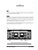

D.W. FEARN
VT-7 Compression Amplifier
27
6.
MAINTENANCE
The VT-7 is built with only the highest quality parts and will prove to be extremely reliable.
Vacuum tubes and electrolytic capacitors, however, have a finite useful life and must be
replaced eventually.
T
op/Bottom Co
ver Removal
Removing the top cover allows access to the vacuum tubes and some of the calibration con-
trols. The top cover allows access to the VU meter calibration controls. Sixteen 6-32 phillips-
head screws must be removed. When replacing the cover, position it so that the slotted ven-
tilation holes are over the tubes (towards the back on the VT-7).
V
acuum Tubes
Eight tubes are used in the VT-7. Six are 6N1P and two are 6072A. There can be as much
as a 15 dB difference in noise level among an assortment of tubes, and the 6072A tubes used
should be carefully chosen to maintain low noise. Selected low-noise tubes are available from
D. W. Fearn. The 6N1P tubes are far less critical and almost any quality off-the-shelf tube will
perform satisfactorily.
Tube life is difficult to predict, but it will probably be measured in years. Catastrophic tube
failure is rare with this type of device, but a gradual increase in noise, microphonics, distor-
tion, or a reduction in headroom, should indicate the need for replacement. It is recommend-
ed that you periodically perform a quick noise and distortion check on the VT-7 and compare
the results to previous measurements.
Tubes also sometimes develop a microphonic response — they will respond to ambient noise
and vibration. This can be an insidious problem since measurements in a quiet room will indi-
cate perfect performance. Gently tapping the tube shields while listening to the output at a
normal monitor level should reveal nothing more than a slight “clank.” On a peak-reading
meter connected to the VT-7 output, with unity gain, any microphonic response above -55
dBm is excessive. Replacement is indicated unless the VT-7 always operates in a quiet and
vibration-free environment.