D.W.
How to Contact us: Telephone: 610-793-2526 Fax: 610-793-1479 Mail: P.O. Box 57, Pocopson, PA 19366 U.S.A. Shipping Address: 182 Bragg Hill Road West Chester, PA 19382 U.S.A. e-mail: dwfearn@dwfearn.com www.dwfearn.com D.W.
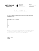
D.W. FEARN www.dwfearn.com H AND - CRAFTED PROFESSIONAL RECORDING EQUIPMENT P.O. Box 57 Pocopson, PA 19366 U.S.A. Tel: 610-793-2526 Fax: 610-793-1479 Certificate of RoHS Compliance D.W. Fearn is committed to manufacturing products that are fully-compliant with the EU RoHS Directive.
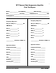
5 VT-7 Vacuum Tube Compression Amplifier Final Test Report Model _______________ Serial Number_______________Mains Voltage ______________ Date ___________________ Tested by ________ VU Calibrated to _______________ dBm Test Equipment _______________________________________________________________ Channel B Channel A Frequency Response: Frequency Response: 20 cps to 20 kc/s +/- ___________ dB 20 cps to 20 kc/s +/- ___________ dB THD+Noise: THD+Noise: 20 cps ______________ % 20 cps ______________ %
7 Table of Contents Final Test Report ............................................................................3 Warranty .........................................................................................7 History of the VT-7 .........................................................................9 1. Specifications ..........................................................................11 2. Description...............................................................................13 3.
8 D.W. Fearn shall not be liable for technical or editorial errors or omissions in this manual, nor for incidental or consequential damages resulting from the use of this material. This instruction manual contains information protected by copyright. No part of this manual may be photocopied or reproduced in any form without prior written consent from D.W. Fearn. Copyright ©2005 D.W. Fearn & Associates D.W.
9 Limited 5-Year Warranty During the warranty period, D.W. Fearn will, at no additional charge, repair or replace defective parts with new parts. This warranty does not extend to any VT-7 that has been damaged or rendered defective as a result of accident, misuse, or abuse; by the use of parts not manufactured or supplied by D.W. Fearn; or by unauthorized modification of the VT-7. Vacuum tubes are excepted from the 5-year warranty, but are warranted for 90 days from date of purchase.
11 History of the VT-7 Compression Amplifier Compression (or limiting) is sometimes seen as a necessary evil in the recording process. Often it is used to compensate for less than optimum performance or recording technique. However, when used appropriately, there is no question that good-sounding compression can add loudness, power, and improved impact to a recording. Over many years of recording, I have had the opportunity to use and sometimes own some of the best compressors in the world. For the D.W.
12 A look inside the VT-7 reveals a very full box with several densely-packed circuit boards for the gain control driver circuitry, interspersed with eight vacuum tubes. Because of the very high frequencies involved in the control circuitry, there are many surface-mount (SMT) components. Thus, the VT-7 is a combination of the latest technology, where needed, with a classic great-sounding vacuum tube audio path. The VT-7 was designed from the beginning to be a stereo compressor.
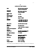
13 1. S P E C I F I C AT I O N S Input Input Load Impedance Nominal Input Level Maximum Input Level @ 20 cps Gain Frequency Response THD + Noise Signal to Noise Ratio Output Output source impedance Maximum Output Level Gain Reduction Range Power Requirements Dimensions Weight Shipping Weight: 600 ohm source (nominal) balanced or unbalanced 32k ohms, transformer balanced bridging +4 dBm +25 dBm unity to +15dB ± 0.2 dB 20 cps to 20 kc ± 0.5 dB 11 cps to 28 kc -3 dB @ 0.5 cps & 65 kc <0.
15 2. DESCRIPTION The Model VT-7 Vacuum Tube Compression Amplifier is designed to provide recording professionals with a sonically superior signal processing device. It is typically used in sound recording studios for processing individual tracks or, when the channels are linked, as a stereo compressor. The inputs and outputs are at line level. The VT-7 in many ways recreates the sound of the classic tube compressors of the 1960s, but using modern gain control circuitry.
16 D.W.
17 3. I N S TA L L AT I O N The VT-7 is carefully packed for shipment and it should survive all but the most brutal handling. If there is any damage, keep the shipping material for use during any possible claim for damage with the shipper. You might also want to keep the box and packaging material in case you ever have to ship the VT-7. Included in the box: 1) The VT-7 Compression Amplifier 2) Line cord 3) This instruction manual Mounting The VT-7 is designed for installation in a standard 19 inch rack.
18 Power The VT-7 is designed to operate from 100, 120, or 220-240 volt, 50/60 Hz power. The unit will be shipped for the voltage specified in the order, but may be changed in the field if necessary. (See the Maintenance section for detailed instructions on changing the primary voltage). The ground pin of the power cord is internally connected to the chassis. This configuration is standard in professional equipment and is required by most electrical codes.
19 4. O P E R AT I O N Input Since the input cable will be carrying high quality audio, it is important that a well-shielded cable is used. You should strive to minimize the number connectors, patch jacks, switches, etc. between the source and the VT-7 input. Output The output of the VT-7 is line level, transformer balanced. Note that vacuum tube equipment is more sensitive to load impedance than solid state units. The VT-7 design was optimized for feeding a balanced bridging input (20k ohms or greater).
20 CONTROLS (see Figure 2.) Threshold The Threshold control adjusts the point where compression begins. With the con- trol all the way down, there is no compression and the VT-7 operates as a straight amplifier. As the control is turned clockwise, the amount of compression increases. This can be monitored on the VU meter (in the GR position), or by ear. Gain Whenever compression is applied, the signal is reduced in level by the amount of gain reduction.
21 You can run a stereo signal with the switch in the Separate position for an effect. On a stereo pair such as a piano or other sub-mix stereo source, the image will tend to shift from left to right as the signal becomes louder in one channel compared to the other. This would be disconcerting on a stereo bus, but it could be interesting on individual stereo tracks. With very fast Attack and/or Release times, low-frequency distortion can often be reduced significantly using the Link HPF position.
22 For 100 volt operation, internal wiring changes must be made. Contact the factory if this becomes necessary. Units ordered for 100 volt operation will be wired for that voltage only. Fuse The center part of the voltage selector is a fuseholder. For 100 and 120 volt operation, the fuse is 2 amps. For 240 volt operation it is 1 amp. See the Maintenance section for fuse replacement information. Bench Test If desired, test the VT-7 before installation.
23 Semi-professional equipment frequently uses a reference level of -10 dBv (roughly 14 dB lower than pro equipment). Although the VT-7 can feed the unbalanced, -10 dBv inputs of semi-pro gear with no difficulty, the VT-7 VU meter will have to be recalibrated in order to be useful. (See Section 6 - Maintenance.) Use your ears to find the setting that sounds best to you for any given sound. SUGGESTIONS: You have chosen to use the VT-7 because of the superior sound it provides.
25 5. T H E O RY O F O P E R AT I O N Input section Line level (low source impedance, balanced, +4 dBm nominal) audio enters through the XLR3 female INPUT connector to a bridging input transformer. The load imposed on the source is 32k ohms and is constant regardless of the frequency. Input transformer The input transformer is made by Jensen Transformers, Inc. and represents the state of the art in transformer design.
26 Second stage The output of the first stage is coupled to the grid of the second stage through a polypropylene capacitor. This stage operates as a Class A voltage amplifier with a gain of approximately 20. Output Stage The output stage operates as a cathode follower, followed by a custom output transformer built for D.W. Fearn by Jensen Transformers, Inc. The output impedance is 115 ohms.
27 6. MAINTENANCE The VT-7 is built with only the highest quality parts and will prove to be extremely reliable. Vacuum tubes and electrolytic capacitors, however, have a finite useful life and must be replaced eventually. Top/Bottom Cover Removal Removing the top cover allows access to the vacuum tubes and some of the calibration controls. The top cover allows access to the VU meter calibration controls. Sixteen 6-32 phillipshead screws must be removed.
28 Although you could purchase a batch of 6072A tubes and select the quietest one(s), it may be cost effective to buy a low-noise tube from the us. Current prices are $76.00 for a selected low-noise 6072A, and $20.00 for a tested 6N1P. (See www.dwfearn.com for the latest prices.) We test the tubes in a VT-7 after a burn-in period and grade them according to noise, microphonic response, distortion, and other characteristics. A low-noise tube from us will meet the original VT-7 specifications.
29 Gain Reduction meter calibration The adjustments for the VU meter “0” calibration in the “GR” position are located on the PWM board. Contact the factory for complete adjustment instructions. Note that the meter calibration can be off but the VT-7 will continue to operate normally otherwise. Some drifting of this adjustment is normal, and the reading will change as the VT-7 warms up over a period of an hour or so.