D.W.
How to Contact us: Telephone: 610-793-2526 Fax: 610-793-1479 Mail: P.O. Box 57, Pocopson, PA 19366 U.S.A. Shipping Address: 182 Bragg Hill Road West Chester, PA 19382 U.S.A. e-mail: dwfearn@dwfearn.com www.dwfearn.
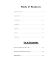
Ta b l e o f C o n t e n t s History of the VT-3 ................................................................................ 7 Specifications.......................................................................................... 9 Description..............................................................................................11 Installation ..............................................................................................13 Operation .............................................
Notice D.W. Fearn shall not be liable for technical or editorial errors or omissions in this manual, nor for incidental or consequential damages resulting from the use of this material. This instruction manual contains information protected by copyright. No part of this guide may be photocopied or reproduced in any form without prior written consent from D.W. Fearn. Copyright ©2006 D.W.
L I M I T E D 5 -Y E A R WA R R A N T Y During the warranty period, D.W. Fearn will, at no additional charge, repair or replace defective parts with new parts. This warranty does not extend to any VT-3 that has been damaged or rendered defective as a result of accident, misuse, or abuse; by the use of parts not manufactured or supplied by D.W. Fearn; or by unau- thorized modification of the VT-3. Vacuum tubes are excluded from the 5-year warranty, but are warranted for a period of 90 days.
7 H i s t o r y o f t h e V T - 3 Va c u u m T u b e D I As far back as I can remember, taking instruments “direct” has never sounded very good to me. There always seemed to be a lack of dynamics, and a sterile qual- ity to sounds recorded with a direct box (or DI). The first tube DI that we produced was the VT-I/F Instrument Interface. It was a beautiful piece, in a large, machined-aluminum case that you could drive a truck over.
8 This prototype was evaluated by a number of studio friends, who made some useful suggestions. These suggestions were incorporated into the second prototype, and the VT-3 design was complete. By the way, our evaluators were very, very reluctant to return the prototype. Why does the VT-3 sound so good? For one thing, it provides the proper load to the instrument. This is vital for an unrestricted sound. The frequency response is flat from 10 cps to 20 kc, with -3 dB points at 0.5 cps and 90 kc.
9 Specifications (with 200 mV input) Input 200 mV nominal unbalanced Input Load Impedance 1 megohm minimum Minimum Input Level 5 mV nominal Maximum Input Level Gain Frequency Response 2.3 volts P-P for 1% THD -10 dB +/- 0.2 dB 10 cps to 20 kc -3 dB @ 0.5 cps and 95 kc THD + Noise <0.3% 20 cps to 20 kc Intermodulation Distortion <0.
10 VT-I/F Vacuum Tube Instrument Interface D.W.
11 Description The D.W. Fearn model VT-3 Vacuum Tube DI is designed to provide recording professionals with a sonically superior method for recording electric and electronic musical instruments by direct injection (DI). Any instrument designed to oper- ate into a “guitar amp” will work perfectly with the VT-3. Typical instruments include: electric bass, electric guitar, electric piano, acoustic instruments with a pickup (piano, acoustic guitar, electric violin, etc.), synthesizers, and samplers.
13 Installation The VT-3 is carefully packed for shipment and should survive all but the most brutal handling. If there is any damage, keep the shipping material for use during any claim for damage with the shipper. Included in the box: 1) The VT-3 DI 2) Line cord 3) This instruction manual Mounting The VT-3 is designed to be rack-mounted. In most cases, cooling will not be a problem, but avoid placing the unit where it is tightly confined. Do not block the cooling holes on the top.
14 are required. The ground pin of the power cord is internally connected to the chas- sis. This configuration is standard in professional equipment and is required by most electrical codes. If ground loop hum is detected, a careful check of the studio grounding scheme is needed. The VT-3 is less susceptible to grounding prob- lems than many studio devices. The Fuse (2) is a 3AG-type 1 amp for 100/120 VAC operation, and 0.5 amp for 220 volts.
15 connectors at all times. It is not good practice to use both the front and rear con- nectors at the same time, although it may be possible under some conditions. Both outputs should feed similar balanced mic inputs. Some loss of quality will result whenever mic inputs are paralleled. Fig. 1 VT-3 Rear Panel Controls and Connections 12 9 6 D.W.
16 Grounding and Shields A full discussion of proper studio wiring schemes is beyond the scope of this manual, but, in general, the shield should be connected to pin 1 of the output connector. The shield should be connected to ground at only one end; however, although not recommended, the shields can often be connected at both ends without a problem. VT-I/F Vacuum Tube Instrument Interface D.W.
17 O P E R AT I O N FRONT PANEL CONTROLS (see Figure 2) Power switch (11) Primary power is applied to the VT-3 circuits when the Power switch (11) is in the up position. The amber pilot lamp (12) on the front panel indicates that the unit is on. It takes about twenty seconds for the VT-3 to start working, but it is suggested that you turn on the power at least five minutes prior to use. The tubes are often noisy until all the internal elements reach a stable operating temperature.
18 Fluorescent lights and SCR dimmers are terrible electrical noise generators. Turn off the fluorescents. If SCR dimmers must be used, they will generally produce the least noise in their full-on (brightest) position. Another source of these hums and buzzes is ground loops caused by the interconnection of various AC (mains) powered equipment.
19 1. The VT-3 must be located near the instrument. Ten feet of cable between the instrument and the VT-3 should be considered the maximum. 2. Use the best quality cables you can. We don’t believe you have to use esoteric wire, but do use good quality, well-shielded cables. The input cable shielding is particularly important. The output cable should be a standard balanced mic cable designed for use with low-Z microphones. Gold-contact phone and XLR connectors are recommended.
20
21 T H E O RY O F O P E R AT I O N This circuit description refers to only one channel. Both channels are identical, sharing only the power supply. (See Figure 3.) Input section The INSTRUMENT input jack is fed directly to the grid of the first amplifier stage, a selected 6N1P. The input impedance is very high (1 megohm) for proper loading of the musical instrument. The first stage is capacitively-coupled to the grid of the output stage.
22 The GND LIFT switch disconnects pin 1 of the OUTPUT connector from the internal ground when the switch is in the up position. Power Supplies Primary power from the AC mains is connected to the VT-3 through a standard IEC power input connector. The Power switch energizes all power supplies. A fuse, accessible on the rear panel, protects the VT-3. and a recessed slide switch provides quick switching between 120VAC and 220-240VAC operation.
23 MAINTENANCE The VT-3 is built with only the highest quality parts and will prove to be extremely reliable. Vacuum tubes and electrolytic capacitors, however, have a finite useful life and must be periodically replaced. Typical tube life with average usage should be at least 5 years. Electrolytic filter capacitors should be good for at least 10 years. TOP COVER REMOVAL Removing the top cover allows access to the vacuum tubes. Twelve 6-32 phillips-head screws must be removed.
24 microphonic response above -55 dBm is excessive. Replacement is indicated unless the VT-3 always operates in a quiet and vibration-free environment. Although you could purchase a batch of 6N1Ps and select the quietest one(s), it may be cost effective to buy a low-noise tube from the us. See our web site (www.dwfearn.com) for current prices. We test the tubes in a VT-3 after a burn-in period and grade them according to noise, microphonic response, and other characteristics.
25 repair experience, you may return the VT-3 to the factory for repair. Call first, however, for shipping information. WARRANTY REPAIR If the VT-3 should develop a problem during the five-year warranty period, call the factory for return shipping instructions. We will repair and return your VT-3 quickly. Note that the warranty does not cover vacuum tubes, which must be periodically replaced. D.W.