
User manual


Table Of Contents
- 1 Table of contents1 T
- 2 Package Contents
- 3 Introduction
- 4 System overview
- 5 Control Surfaces
- 6 AXUM Engine
- 6.1 Console 1-4 configuration
- 6.1.1 IP/Clock configuration
- 6.1.2 Global configuration
- 6.1.3 Mix buss configuration
- 6.1.4 Monitor buss configuration
- 6.1.5 Source configuration
- 6.1.6 Extern source configuration
- 6.1.7 Destination configuration
- 6.1.8 Talkback configuration
- 6.1.9 Processing presets
- 6.1.10 Module assignment
- 6.1.11 Module configuration
- 6.1.11.1 Module configuration page
- 6.1.11.2 Module preset 1A/1B, 2A/2B, 3A/3B, 4A/4B
- 6.1.11.3 Processing
- These are the programmed processing defaults for the modules. Depending on the startup settings these processing defaults will be used at startup (programmed defaults in global configuration).The field ‘Use at source select’ determines if the default module processing in the source configuration is used when a source is assigned via the module source select functionality and no processing preset is assigned in the ‘source configuration’.
- The following state/value processing sections are available:
- 6.1.11.4 Routing
- 6.1.11.5 Set module 1 to programmed startup state
- 6.1.12 Mix/monitor buss presets
- 6.1.13 Console presets
- 6.1.14 Surface configuration
- 6.1.15 Rack configuration
- 6.1.16 Source pools
- 6.1.17 Preset pools
- 6.1.18 Users
- 6.2 System configuration
- 6.1 Console 1-4 configuration
- 7 Surface(s) website
- 8 Block diagrams – Must be created
- 9 I/O Rack description
- 10 Available I/O rack cards
- 11 Patch panels
- 12 Specifications AXUM digital audio system
- 13 List Of Figures
- 14 List Of Tables
- 15 Declaration Of Conformity
- 16 Product Safety
- 17 Disclaimer
- 18 Appendix A - Network design for AXUM
- 19 Appendix B – Surface service
- 20 Appendix C – Engine functions
A·X·U·M User Manual Version 2.5 - 2011-01-28
AXUM from D&R - Phone: +31 294 418014 - E-Mail: info@d-r.nl - 82 -
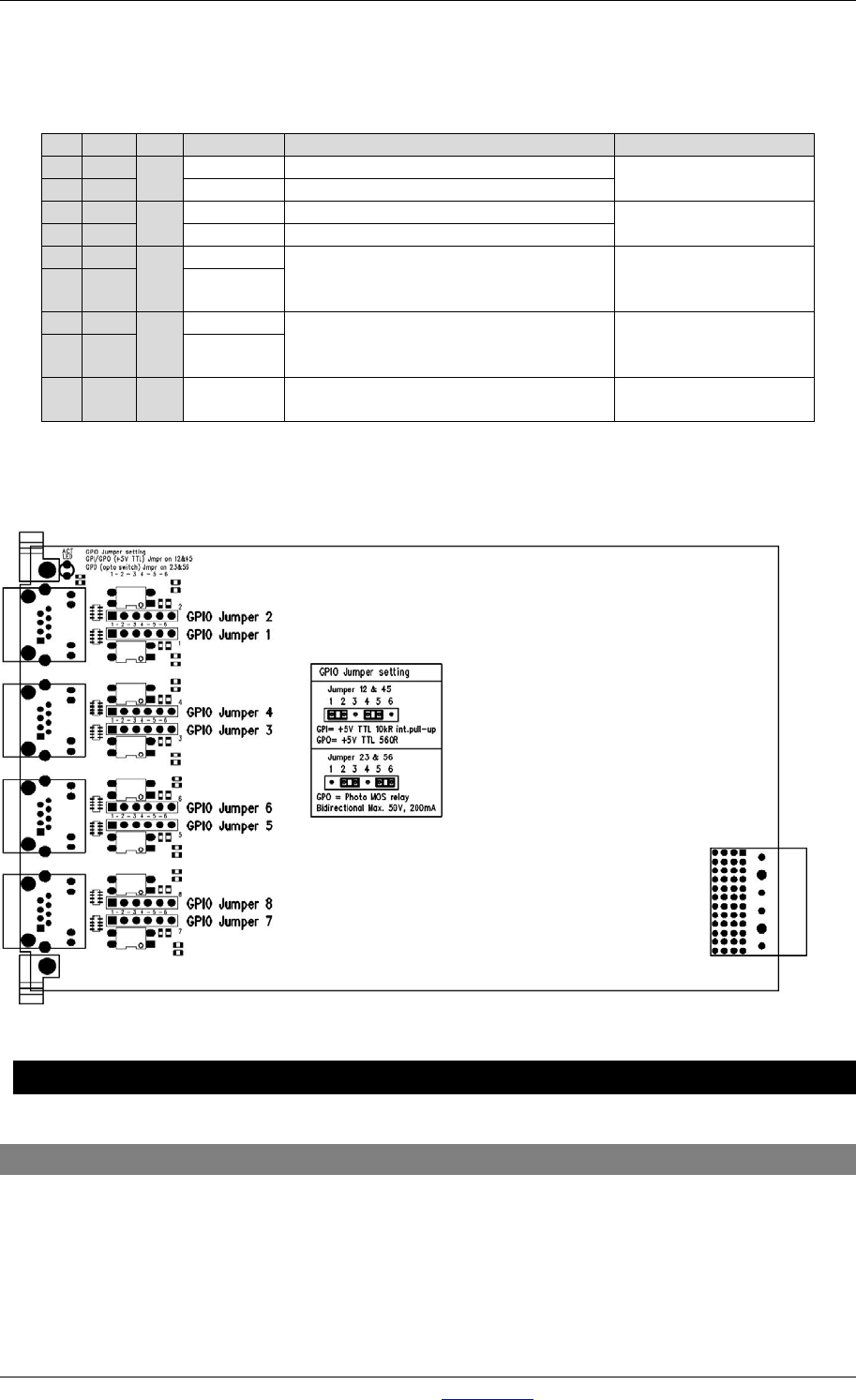
• Relay out (no input available).
this is selected by GPIO1 jumpers in the place 23 and GPIO2 jumpers in place 56. These
jumpers are located on the I/O cards, close to the RJ45 connectors.
Table 11-6: RJ45 pinning in GPO-Relay mode
The figure shows how the jumper selection on the I/O card looks:
Figure 50: GPIO TTL/Relay jumper selection
12 Specifications AXUM digital audio system
12.1 Input/output cards
Mic inputs : Electronically balanced
: Input impedance 2k Ohm
: Input sensitivity -70dBu up to +20dBu (PAD)
: CMRR MIC inputs: 85dB @ 1kHz, maximum gain
: Phantom is switchable +48 Volts
: Optional is transformer balancing
Pin
Con.
Pair
Pin name
Function
Comment
1
1A
1
+Audio 1
Left audio input or output in-phase
specifications
depends on I/O card
2
1B
-Audio 1
Left audio input or output out-phase
3
2A
2
+Audio 2
Right audio input or output in-phase
specifications
depends on I/O card
6
2B
-Audio 2
Right audio input or output out-phase
5
3A
3
GPIO1a
Relay, connecting a&b
Photo MOS relay
Bidirectional Max.
50V, 200mA
4 3B GPIO1b
7
4A
4
GPIO2a
Relay, connecting a&b
Photo MOS relay
Bidirectional Max.
50V, 200mA
8 4B GPIO2b
S GND S Shield GND
Audio ground and
reference for GP-In