
User manual


Table Of Contents
- 1 Table of contents1 T
- 2 Package Contents
- 3 Introduction
- 4 System overview
- 5 Control Surfaces
- 6 AXUM Engine
- 6.1 Console 1-4 configuration
- 6.1.1 IP/Clock configuration
- 6.1.2 Global configuration
- 6.1.3 Mix buss configuration
- 6.1.4 Monitor buss configuration
- 6.1.5 Source configuration
- 6.1.6 Extern source configuration
- 6.1.7 Destination configuration
- 6.1.8 Talkback configuration
- 6.1.9 Processing presets
- 6.1.10 Module assignment
- 6.1.11 Module configuration
- 6.1.11.1 Module configuration page
- 6.1.11.2 Module preset 1A/1B, 2A/2B, 3A/3B, 4A/4B
- 6.1.11.3 Processing
- These are the programmed processing defaults for the modules. Depending on the startup settings these processing defaults will be used at startup (programmed defaults in global configuration).The field ‘Use at source select’ determines if the default module processing in the source configuration is used when a source is assigned via the module source select functionality and no processing preset is assigned in the ‘source configuration’.
- The following state/value processing sections are available:
- 6.1.11.4 Routing
- 6.1.11.5 Set module 1 to programmed startup state
- 6.1.12 Mix/monitor buss presets
- 6.1.13 Console presets
- 6.1.14 Surface configuration
- 6.1.15 Rack configuration
- 6.1.16 Source pools
- 6.1.17 Preset pools
- 6.1.18 Users
- 6.2 System configuration
- 6.1 Console 1-4 configuration
- 7 Surface(s) website
- 8 Block diagrams – Must be created
- 9 I/O Rack description
- 10 Available I/O rack cards
- 11 Patch panels
- 12 Specifications AXUM digital audio system
- 13 List Of Figures
- 14 List Of Tables
- 15 Declaration Of Conformity
- 16 Product Safety
- 17 Disclaimer
- 18 Appendix A - Network design for AXUM
- 19 Appendix B – Surface service
- 20 Appendix C – Engine functions
A·X·U·M User Manual Version 2.5 - 2011-01-28
AXUM from D&R - Phone: +31 294 418014 - E-Mail: info@d-r.nl - 81 -
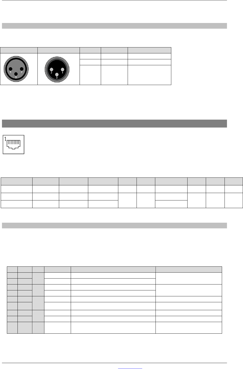
11.2.4 Stereo line input and output
The line I/O jack patch panel houses female jack connecters, the line I/O XLR patch panel houses
XLR type connectors (male or female).
Female XLR
Male XLR
Name
Function
Pinning
2
+Audio
Audio in phase
3
-Audio
Audio out phase
1
Shield Ground
Table 11-3: Line I/O patch panel XLR wiring
11.3 Standard RJ45 wiring
Figure 49: RJ45 Connector
Pin 1 Pin 2 Pin 3 Pin 4 Pin 5 Pin 6 Pin 7 Pin 8 Shield
RJ45 name 1A 1B 2A 3B 3A 2B 4A 4B S
Ball Left (Hot) Left (Cold) Right (Hot)
GPIO1 GPIO1
Right (Cold)
GPIO2
GPIO2
Shield
Phones Left 1 Right 1 Left 2 Right 2
Table 11-4: Standard RJ45 wiring
11.3.1 GPIO TTL/Relay selection
Each RJ45 connection on I/O cards handles audio signals and GPIOs.
The GPIO pins can be configured to work as:
• TTL in and out
this is selected by GPIO1 jumpers in the place 12 and GPIO2 jumpers in place 45. These
jumpers are located on the I/O cards, close to the RJ45 connectors.
Table 11-5: RJ45 pinning in GPIO-TLL mode
Pin
Con.
Pair
Pin name
Function
Comment
1
1A
1
+Audio 1
Left audio input or output in-phase
Imp. 2k Ohm
max. level +20dBu
2
1B
-Audio 1
Left audio input or output out-phase
3
2A
2
+Audio 2
Right audio input or output in-phase
Imp. 2k Ohm
max. level +20dBu
6
2B
-Audio 2
Right audio input or output out-phase
5
3A
3
GPIO1a
GP-Out
+5V TTL out, 560R
4 3B GPIO1b GP-In +5V TTL in, 10kR int. pull-up
7
4A
4
GPIO2a
GP-Out
+5V TTL out, 560R
8
4B
GPIO2b
GP-In.
+5V TTL in, 10kR int. pull-up
S GND S Shield GND
Audio ground and reference
for GP-In