
User manual


Table Of Contents
- 1 Table of contents1 T
- 2 Package Contents
- 3 Introduction
- 4 System overview
- 5 Control Surfaces
- 6 AXUM Engine
- 6.1 Console 1-4 configuration
- 6.1.1 IP/Clock configuration
- 6.1.2 Global configuration
- 6.1.3 Mix buss configuration
- 6.1.4 Monitor buss configuration
- 6.1.5 Source configuration
- 6.1.6 Extern source configuration
- 6.1.7 Destination configuration
- 6.1.8 Talkback configuration
- 6.1.9 Processing presets
- 6.1.10 Module assignment
- 6.1.11 Module configuration
- 6.1.11.1 Module configuration page
- 6.1.11.2 Module preset 1A/1B, 2A/2B, 3A/3B, 4A/4B
- 6.1.11.3 Processing
- These are the programmed processing defaults for the modules. Depending on the startup settings these processing defaults will be used at startup (programmed defaults in global configuration).The field ‘Use at source select’ determines if the default module processing in the source configuration is used when a source is assigned via the module source select functionality and no processing preset is assigned in the ‘source configuration’.
- The following state/value processing sections are available:
- 6.1.11.4 Routing
- 6.1.11.5 Set module 1 to programmed startup state
- 6.1.12 Mix/monitor buss presets
- 6.1.13 Console presets
- 6.1.14 Surface configuration
- 6.1.15 Rack configuration
- 6.1.16 Source pools
- 6.1.17 Preset pools
- 6.1.18 Users
- 6.2 System configuration
- 6.1 Console 1-4 configuration
- 7 Surface(s) website
- 8 Block diagrams – Must be created
- 9 I/O Rack description
- 10 Available I/O rack cards
- 11 Patch panels
- 12 Specifications AXUM digital audio system
- 13 List Of Figures
- 14 List Of Tables
- 15 Declaration Of Conformity
- 16 Product Safety
- 17 Disclaimer
- 18 Appendix A - Network design for AXUM
- 19 Appendix B – Surface service
- 20 Appendix C – Engine functions
A·X·U·M User Manual Version 2.5 - 2011-01-28
AXUM from D&R - Phone: +31 294 418014 - E-Mail: info@d-r.nl - 79 -
11.2 Wiring
11.2.1 GPIO/Remote
The remote jack connects to all kinds of remote in-/outputs. Such as remote start/stop, external red
lights or cough. The function of the remote jack depends on the I/O card and function setup for this
GPIO. The software determines its function and where it is connected to.
! NEVER CONNECT HIGH POWER VOLTAGE (WALL POWER) TO THE REMOTE-JACK !
If the GPIO jumper setting on the Axum-Rack-Board is set for GPO the remote becomes only a
Remote-Output by a build in Solid State Relay. The relay is situated between Tip and Ring of the
remote jack.
Normally the GPIO jumper setting on the Axum-Rack-boards are set for GPO.
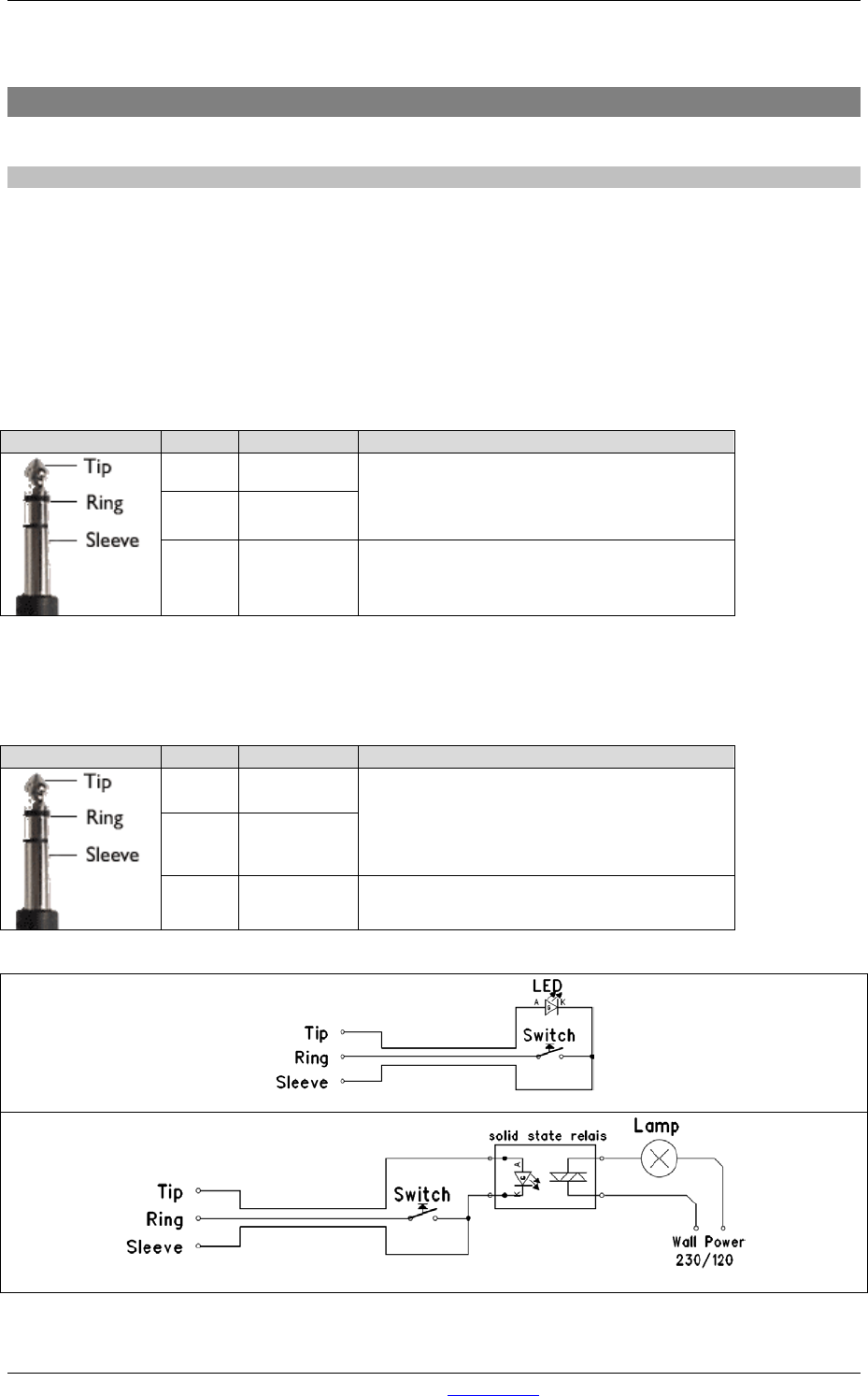
Jack
Name
function
Comment
Tip GP-CC
GPIO Jumper 23 & 56:
Photo MOS relay (max 50V, 200mA)
Ring GP-NO
Sleeve Shield Ground
Table : GPO Patch Panel wiring
If the GPIO jumper setting on the Axum-rack-Board is set for GPIO the remote becomes a Remote-
Output GPO (+5V TTL) on the Tip of the remote jack and a Remote-Input GPI (+5V TTL internal pull-
up) on the Ring. The Sleeve is Shield and the ground for the TTL signal.
Jack
Name
function
Comment
Tip GP-Output
GPIO Jumper 12 & 45:
GPO: +5V, 560R Ohm
GPI: max. +5V with 10k internal pull-up.
Ring GP-Input
Sleeve Shield Ground
Table : GPIO Patch Panel wiring
GPIO connection example for MicOn-LED and cough-switch remote.
GPIO connection example for OnAir-Lamp and TB-Switch remote.