
User manual


Table Of Contents
- 1 Table of contents1 T
- 2 Package Contents
- 3 Introduction
- 4 System overview
- 5 Control Surfaces
- 6 AXUM Engine
- 6.1 Console 1-4 configuration
- 6.1.1 IP/Clock configuration
- 6.1.2 Global configuration
- 6.1.3 Mix buss configuration
- 6.1.4 Monitor buss configuration
- 6.1.5 Source configuration
- 6.1.6 Extern source configuration
- 6.1.7 Destination configuration
- 6.1.8 Talkback configuration
- 6.1.9 Processing presets
- 6.1.10 Module assignment
- 6.1.11 Module configuration
- 6.1.11.1 Module configuration page
- 6.1.11.2 Module preset 1A/1B, 2A/2B, 3A/3B, 4A/4B
- 6.1.11.3 Processing
- These are the programmed processing defaults for the modules. Depending on the startup settings these processing defaults will be used at startup (programmed defaults in global configuration).The field ‘Use at source select’ determines if the default module processing in the source configuration is used when a source is assigned via the module source select functionality and no processing preset is assigned in the ‘source configuration’.
- The following state/value processing sections are available:
- 6.1.11.4 Routing
- 6.1.11.5 Set module 1 to programmed startup state
- 6.1.12 Mix/monitor buss presets
- 6.1.13 Console presets
- 6.1.14 Surface configuration
- 6.1.15 Rack configuration
- 6.1.16 Source pools
- 6.1.17 Preset pools
- 6.1.18 Users
- 6.2 System configuration
- 6.1 Console 1-4 configuration
- 7 Surface(s) website
- 8 Block diagrams – Must be created
- 9 I/O Rack description
- 10 Available I/O rack cards
- 11 Patch panels
- 12 Specifications AXUM digital audio system
- 13 List Of Figures
- 14 List Of Tables
- 15 Declaration Of Conformity
- 16 Product Safety
- 17 Disclaimer
- 18 Appendix A - Network design for AXUM
- 19 Appendix B – Surface service
- 20 Appendix C – Engine functions
A·X·U·M User Manual Version 2.5 - 2011-01-28
AXUM from D&R - Phone: +31 294 418014 - E-Mail: info@d-r.nl - 78 -
11 Patch panels
All distribution of audio within the AXUM digital audio system is with shielded twisted pair cable.
The Breakout 19” panels, you need to connect equipment use standard audio connectors.
11.1 19” Patch panels / Breakout panels
The AXUM 19” Break out patch panels convert the RJ45 Shielded connection to the industry standard
connectors such as XLR and Jack. There are various patch panels available for the AXUM for
example:
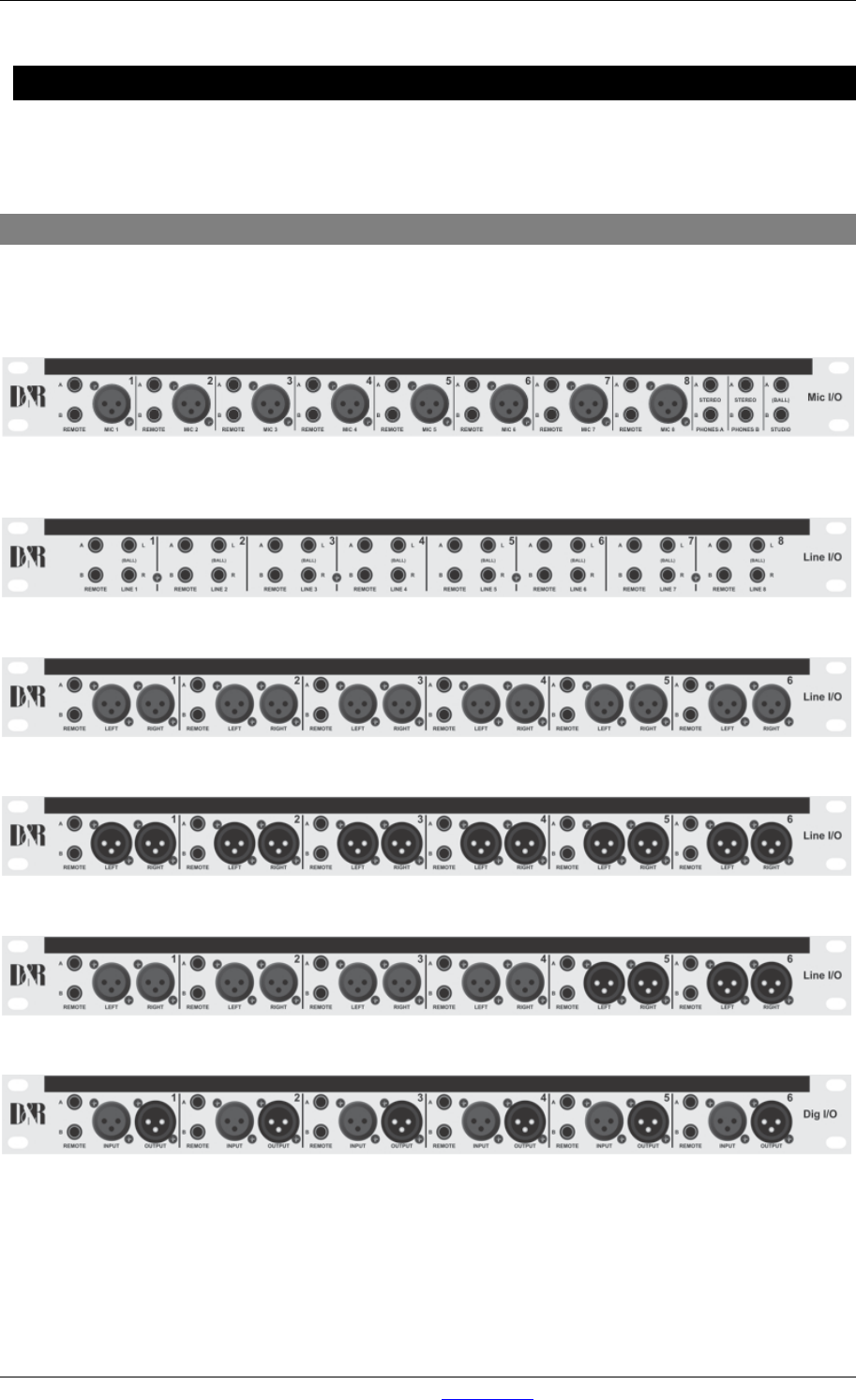
60882045, The MIC I/O with 8 MIC XLR, 16 remote jacks, 4 stereo phone jacks, 2 Line out jacks.
60882046, Line I/O jack with 16 balanced Line in/out jack and 16 remote jacks.
60882047, Line input XLR with 12 balanced Line in XLRs (female) and 12 remote jacks.
60882048, Line output XLR with 12 balanced Line out XLRs (male) and 12 remote jacks.
60882049, Line I/O XLR with 8 balanced Line in XLRs (female), 4 balanced Line out XLRs (male) and 12 remote jacks.
60882050, Dig I/O with 6 stereo digital inputs and 6 stereo digital outputs.
Figure 48: AXUM Break out Panels