
User manual


Table Of Contents
- 1 Table of contents1 T
- 2 Package Contents
- 3 Introduction
- 4 System overview
- 5 Control Surfaces
- 6 AXUM Engine
- 6.1 Console 1-4 configuration
- 6.1.1 IP/Clock configuration
- 6.1.2 Global configuration
- 6.1.3 Mix buss configuration
- 6.1.4 Monitor buss configuration
- 6.1.5 Source configuration
- 6.1.6 Extern source configuration
- 6.1.7 Destination configuration
- 6.1.8 Talkback configuration
- 6.1.9 Processing presets
- 6.1.10 Module assignment
- 6.1.11 Module configuration
- 6.1.11.1 Module configuration page
- 6.1.11.2 Module preset 1A/1B, 2A/2B, 3A/3B, 4A/4B
- 6.1.11.3 Processing
- These are the programmed processing defaults for the modules. Depending on the startup settings these processing defaults will be used at startup (programmed defaults in global configuration).The field ‘Use at source select’ determines if the default module processing in the source configuration is used when a source is assigned via the module source select functionality and no processing preset is assigned in the ‘source configuration’.
- The following state/value processing sections are available:
- 6.1.11.4 Routing
- 6.1.11.5 Set module 1 to programmed startup state
- 6.1.12 Mix/monitor buss presets
- 6.1.13 Console presets
- 6.1.14 Surface configuration
- 6.1.15 Rack configuration
- 6.1.16 Source pools
- 6.1.17 Preset pools
- 6.1.18 Users
- 6.2 System configuration
- 6.1 Console 1-4 configuration
- 7 Surface(s) website
- 8 Block diagrams – Must be created
- 9 I/O Rack description
- 10 Available I/O rack cards
- 11 Patch panels
- 12 Specifications AXUM digital audio system
- 13 List Of Figures
- 14 List Of Tables
- 15 Declaration Of Conformity
- 16 Product Safety
- 17 Disclaimer
- 18 Appendix A - Network design for AXUM
- 19 Appendix B – Surface service
- 20 Appendix C – Engine functions
A·X·U·M User Manual Version 2.5 - 2011-01-28
AXUM from D&R - Phone: +31 294 418014 - E-Mail: info@d-r.nl - 70 -
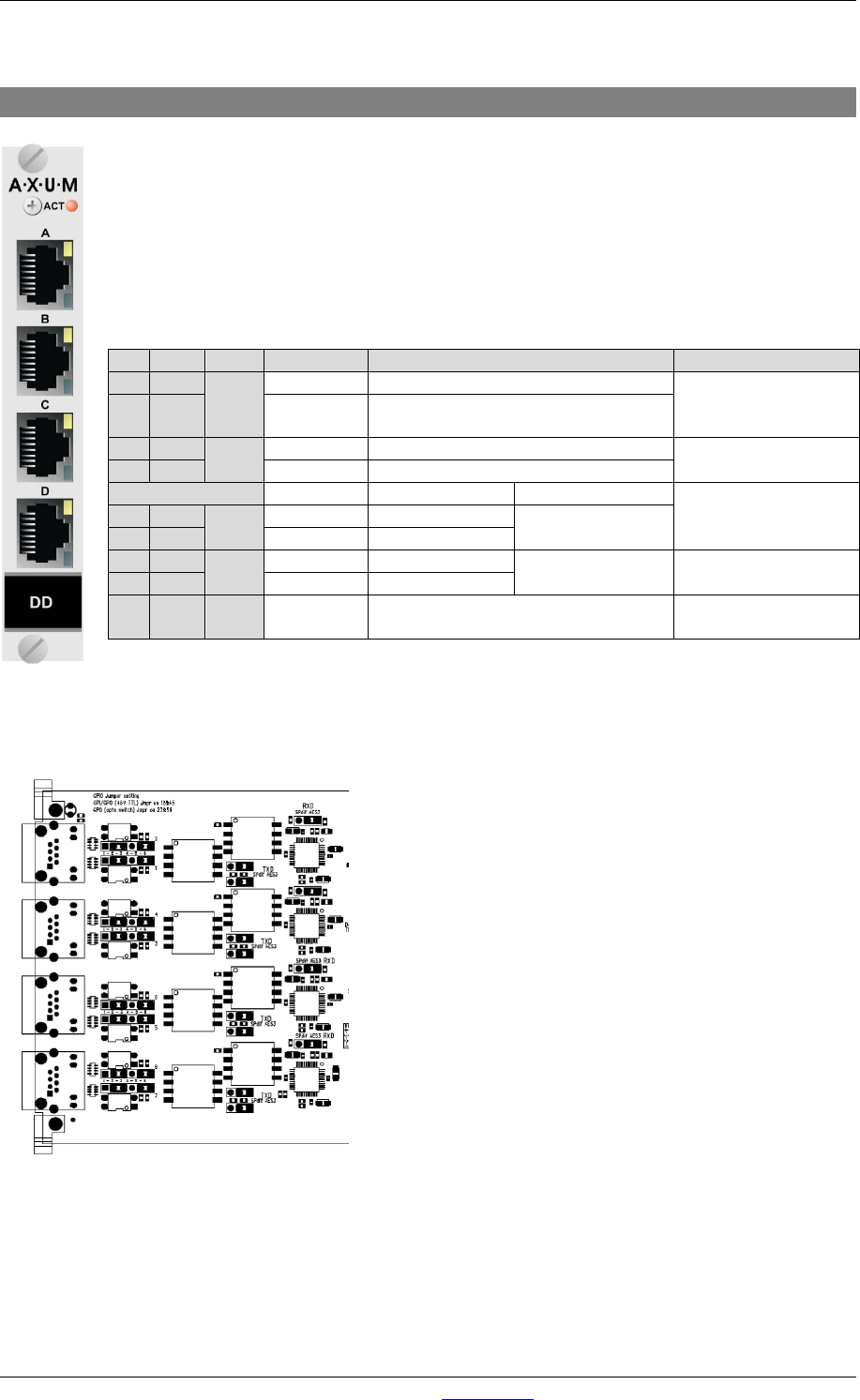
10.3 Digital in/output card (optional SRC)
There are four balanced digital inputs and outputs available on each card.
Each RJ45 connector represents a stereo line input and two GPIO’s which can be
connected to the 19” patch panels with a shielded twisted pair (STP) cable.
There is also a card available with built in sample rate converters (SRC).
For each GPIO you can choose, by way of a hardware jumper on de board, between TTL
Input/output or Photo-MOS relay output see chapter 11.3.1 GPIO TTL/Relay selection. For
software configuration see chapter 9.3 GPIO.
Table 10-3: Digital input/output RJ45 connection
With jumper on the I/O card it is possible to select the impedance for S/P-DIF (75Ω) or AES-3 (110 Ω)
This figures shows the jumper location on the I/O card
Figure 46: Digital S/P-DIF or AES3 selection
Pin
Con.
Pair
Pin name
Function
Comment
1
1A
1
+Audio 1
Digital input in-phase
Imp. 110Ω/75Ω
optional SRC:
32..96kHz
2 1B -Audio 1 Digital input out-phase
3
2A
2
+Audio 2
Digital output in-phase
Imp. 110Ω/75Ω
32, 44.1, 48kHz
6
2B
-Audio 2
Digital output out-phase
If jumper TTL-GPIO If jumper GPO
see chapter 11.3.1
5
3A
3
GPIO1a
GP-Out (TTL)
Photo MOS relay
(max 50V, 200mA)
4
3B
GPIO1b
nGP-In (TTL)
7
4A
4
GPIO2a
GP-Out
(TTL)
Photo MOS relay
(max 50V, 200mA)
see chapter 11.3.1
8
4B
GPIO2b
nGP-In (TTL)
S GND S Shield GND
Audio ground and
reference for GP-In