
User manual


Table Of Contents
- 1 Table of contents1 T
- 2 Package Contents
- 3 Introduction
- 4 System overview
- 5 Control Surfaces
- 6 AXUM Engine
- 6.1 Console 1-4 configuration
- 6.1.1 IP/Clock configuration
- 6.1.2 Global configuration
- 6.1.3 Mix buss configuration
- 6.1.4 Monitor buss configuration
- 6.1.5 Source configuration
- 6.1.6 Extern source configuration
- 6.1.7 Destination configuration
- 6.1.8 Talkback configuration
- 6.1.9 Processing presets
- 6.1.10 Module assignment
- 6.1.11 Module configuration
- 6.1.11.1 Module configuration page
- 6.1.11.2 Module preset 1A/1B, 2A/2B, 3A/3B, 4A/4B
- 6.1.11.3 Processing
- These are the programmed processing defaults for the modules. Depending on the startup settings these processing defaults will be used at startup (programmed defaults in global configuration).The field ‘Use at source select’ determines if the default module processing in the source configuration is used when a source is assigned via the module source select functionality and no processing preset is assigned in the ‘source configuration’.
- The following state/value processing sections are available:
- 6.1.11.4 Routing
- 6.1.11.5 Set module 1 to programmed startup state
- 6.1.12 Mix/monitor buss presets
- 6.1.13 Console presets
- 6.1.14 Surface configuration
- 6.1.15 Rack configuration
- 6.1.16 Source pools
- 6.1.17 Preset pools
- 6.1.18 Users
- 6.2 System configuration
- 6.1 Console 1-4 configuration
- 7 Surface(s) website
- 8 Block diagrams – Must be created
- 9 I/O Rack description
- 10 Available I/O rack cards
- 11 Patch panels
- 12 Specifications AXUM digital audio system
- 13 List Of Figures
- 14 List Of Tables
- 15 Declaration Of Conformity
- 16 Product Safety
- 17 Disclaimer
- 18 Appendix A - Network design for AXUM
- 19 Appendix B – Surface service
- 20 Appendix C – Engine functions
A·X·U·M User Manual Version 2.5 - 2011-01-28
AXUM from D&R - Phone: +31 294 418014 - E-Mail: info@d-r.nl - 66 -
or 1). A value of ‘1’ makes sure that if the GPI is +5V the function is made active. The value ‘0’
makes sure that if the GPI is 0V the function is made active.
When you submit an empty box the object returns to the startup default value.
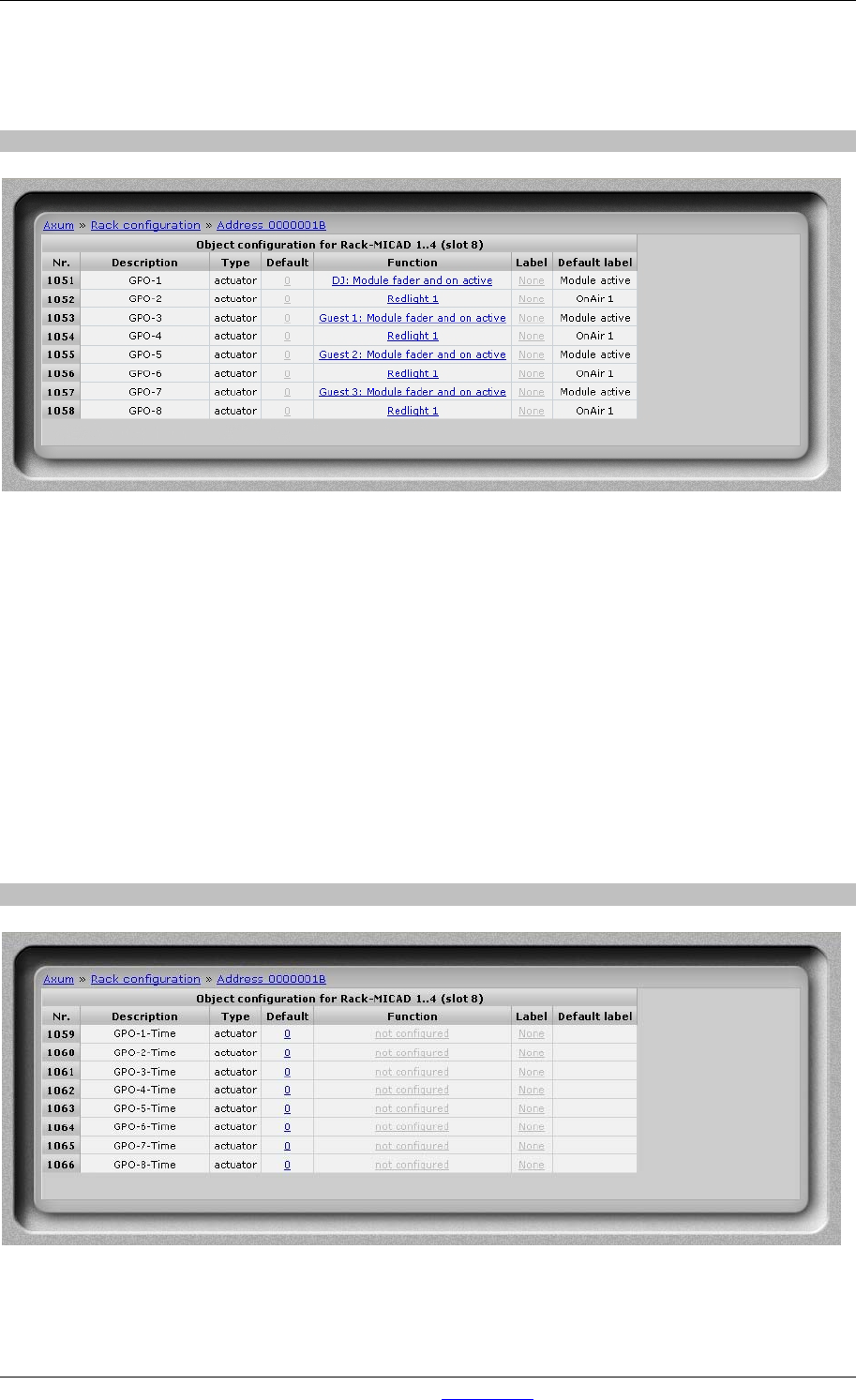
9.3.3 GPO
Figure 43: GPO configuration
• Default
The gray value is the startup default, this may be changed by assigning a custom value(0 or
1). A value of ‘1’ makes sure the GPO is active at startup. A value of ‘0’ makes sure the GPO
is inactive at startup. The GPO output state is also depending on the GPO active-state setting.
When you submit an empty box the object returns to the startup default value.
• Function
Here you may select which engine function is connected to the object. To use the GPO
functions you should maybe change the hardware jumper setting on the board (see chapter
11.3.1 GPIO TTL/Relay selection) to enable the given engine function The default jumper
setting is GPO-Relay for all cards except for the MIC input card. The default jumper setting for
the MIC input card is GPIO-TTL for GPIO 1, 3, 5 and 7 and GPO-Relay for GPIO 2, 4, 6 and
8.
9.3.4 GPO Time
Figure 44: GPO Time configuration
• Default
The gray value is the startup default, this may be changed by assigning a custom value.