
User manual


Table Of Contents
- 1 Table of contents1 T
- 2 Package Contents
- 3 Introduction
- 4 System overview
- 5 Control Surfaces
- 6 AXUM Engine
- 6.1 Console 1-4 configuration
- 6.1.1 IP/Clock configuration
- 6.1.2 Global configuration
- 6.1.3 Mix buss configuration
- 6.1.4 Monitor buss configuration
- 6.1.5 Source configuration
- 6.1.6 Extern source configuration
- 6.1.7 Destination configuration
- 6.1.8 Talkback configuration
- 6.1.9 Processing presets
- 6.1.10 Module assignment
- 6.1.11 Module configuration
- 6.1.11.1 Module configuration page
- 6.1.11.2 Module preset 1A/1B, 2A/2B, 3A/3B, 4A/4B
- 6.1.11.3 Processing
- These are the programmed processing defaults for the modules. Depending on the startup settings these processing defaults will be used at startup (programmed defaults in global configuration).The field ‘Use at source select’ determines if the default module processing in the source configuration is used when a source is assigned via the module source select functionality and no processing preset is assigned in the ‘source configuration’.
- The following state/value processing sections are available:
- 6.1.11.4 Routing
- 6.1.11.5 Set module 1 to programmed startup state
- 6.1.12 Mix/monitor buss presets
- 6.1.13 Console presets
- 6.1.14 Surface configuration
- 6.1.15 Rack configuration
- 6.1.16 Source pools
- 6.1.17 Preset pools
- 6.1.18 Users
- 6.2 System configuration
- 6.1 Console 1-4 configuration
- 7 Surface(s) website
- 8 Block diagrams – Must be created
- 9 I/O Rack description
- 10 Available I/O rack cards
- 11 Patch panels
- 12 Specifications AXUM digital audio system
- 13 List Of Figures
- 14 List Of Tables
- 15 Declaration Of Conformity
- 16 Product Safety
- 17 Disclaimer
- 18 Appendix A - Network design for AXUM
- 19 Appendix B – Surface service
- 20 Appendix C – Engine functions
A·X·U·M User Manual Version 2.5 - 2011-01-28
AXUM from D&R - Phone: +31 294 418014 - E-Mail: info@d-r.nl - 63 -
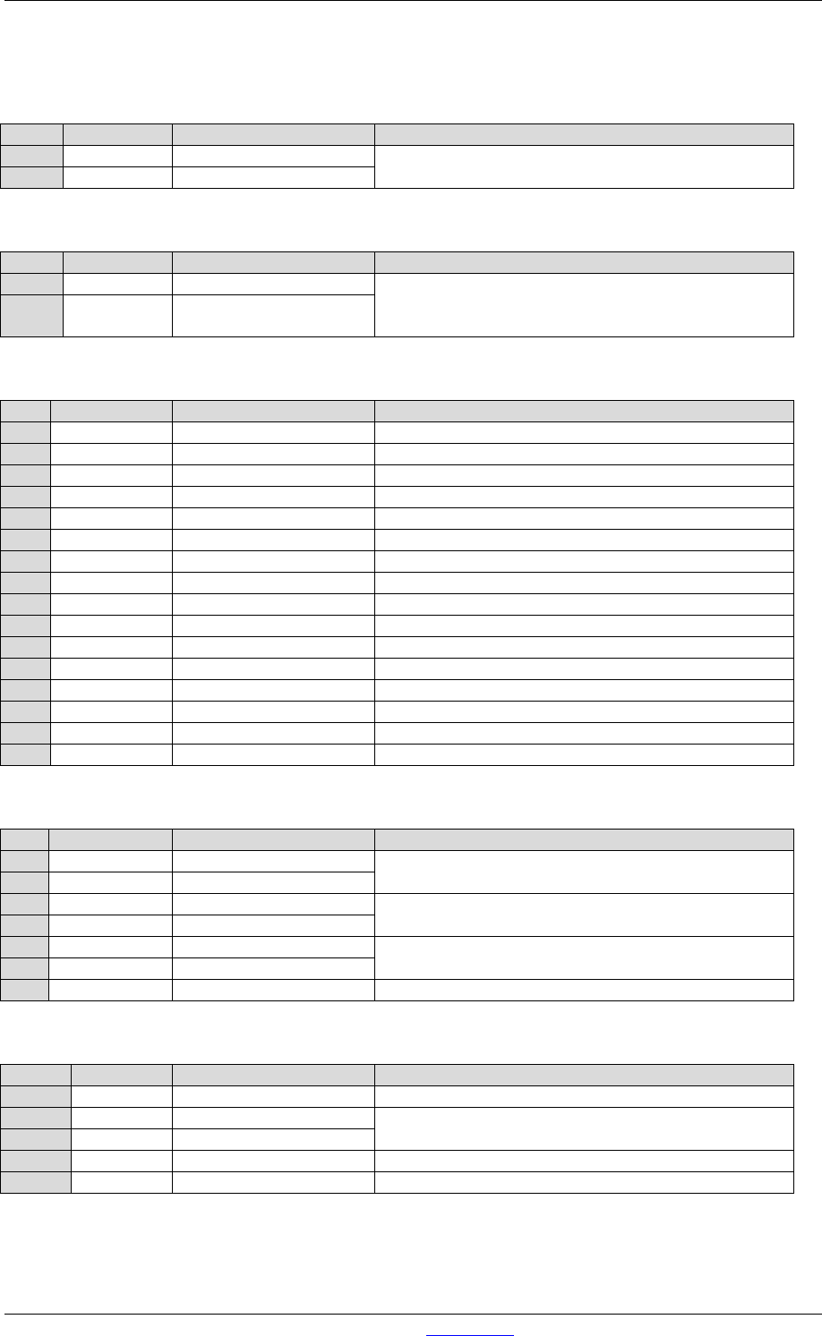
Pin
Pin name
Function
Comment
1
Centre
Frame Clock in
32kHz, 44.1kHz, 48kHz, +/- 100ppm, +5V TTL,
switchable 75Ohm terminator.
GND
GND
Ground Frame Clock in
Table 9-1: Frame clock input BNC
Pin
Pin name
Function
Comment
1
Centre
Frame Clock Out
32kHz, 44.1kHz, 48kHz, +5V TTL, imp.: 75Ohm
GND GND
Ground Frame Clock
out
Table 9-2: Frame clock output BNC
Pin
Pin name
Function
Comment
1
Red
Red Video Out
Red Video
2
Green
Green Video Out
Green Video
3
Blue
Blue Video Out
Blue Video
4
nc
5
GND Hsync
GND Horizontal Sync
6
Red_RTN
Red Video Return
Red Video
7
Green_RTN
Green Video Return
Green Video
8
Blue_RTN
Blue Video Return
Blue Video
9
+5V
Power DDC
DCC
10
GND
GND (Vsync, DCC)
Ground
11
nc
12
DDDA
Data DDC
DCC
13
Hsync
Horizontal Sync
Horizontal Sync
14
Vsync
Vertical Sync
Vertical Sync
15
DDCK
CLK DDC
DCC
S
Shield
Ground
Table 9-3: VGA 15p D-Sub connector
Pin
Pin name
Function
Comment
1
KB Data
Keyboard/Mouse Data
Keyboard/Mouse Connection
5
KB CLK
Keyboard/Mouse CLK
2
not connected
6
4
PWR
+5V Power
Power Connection
3
GND
Ground
S
Shield
Ground
Ground
Table 9-4: Keyboard & Mouse mini DIN connector
Pin
Pin name
Function
Comment
1a/b
VBUS
+5V Power
Supply power
2a/b
nUSB
USB Data outface
USB
3a/b
USB
USB Data inface
4a/b
GND
Ground
Ground
S
Shield
Ground
Ground
Table 9-5: USB connector (2x)