
User manual


Table Of Contents
- 1 Table of contents1 T
- 2 Package Contents
- 3 Introduction
- 4 System overview
- 5 Control Surfaces
- 6 AXUM Engine
- 6.1 Console 1-4 configuration
- 6.1.1 IP/Clock configuration
- 6.1.2 Global configuration
- 6.1.3 Mix buss configuration
- 6.1.4 Monitor buss configuration
- 6.1.5 Source configuration
- 6.1.6 Extern source configuration
- 6.1.7 Destination configuration
- 6.1.8 Talkback configuration
- 6.1.9 Processing presets
- 6.1.10 Module assignment
- 6.1.11 Module configuration
- 6.1.11.1 Module configuration page
- 6.1.11.2 Module preset 1A/1B, 2A/2B, 3A/3B, 4A/4B
- 6.1.11.3 Processing
- These are the programmed processing defaults for the modules. Depending on the startup settings these processing defaults will be used at startup (programmed defaults in global configuration).The field ‘Use at source select’ determines if the default module processing in the source configuration is used when a source is assigned via the module source select functionality and no processing preset is assigned in the ‘source configuration’.
- The following state/value processing sections are available:
- 6.1.11.4 Routing
- 6.1.11.5 Set module 1 to programmed startup state
- 6.1.12 Mix/monitor buss presets
- 6.1.13 Console presets
- 6.1.14 Surface configuration
- 6.1.15 Rack configuration
- 6.1.16 Source pools
- 6.1.17 Preset pools
- 6.1.18 Users
- 6.2 System configuration
- 6.1 Console 1-4 configuration
- 7 Surface(s) website
- 8 Block diagrams – Must be created
- 9 I/O Rack description
- 10 Available I/O rack cards
- 11 Patch panels
- 12 Specifications AXUM digital audio system
- 13 List Of Figures
- 14 List Of Tables
- 15 Declaration Of Conformity
- 16 Product Safety
- 17 Disclaimer
- 18 Appendix A - Network design for AXUM
- 19 Appendix B – Surface service
- 20 Appendix C – Engine functions
A·X·U·M User Manual Version 2.5 - 2011-01-28
AXUM from D&R - Phone: +31 294 418014 - E-Mail: info@d-r.nl - 62 -
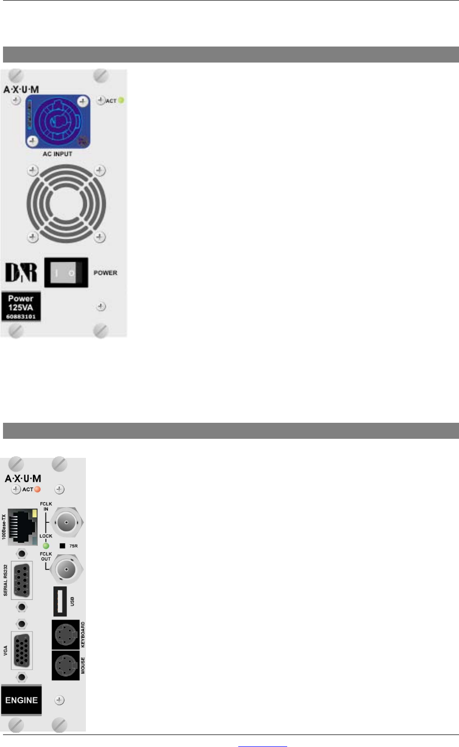
9.1 Power supply
At the far left in the I/O RACK is the position where the power supply
Card is inserted; an optional second power supply card can be inserted
alongside this first one. With two power supplies, you have created
automatic power supply redundancy.
The LED will blink green to show the power supply is up and running.
At failure of the local power, this LED activity will be blinking red or not
blinking at all.
The NEUTRIK
TM
PowerCON
TM
will feed 100-240V power to the supply.
With the power switch you can turn off the local power supply.
WARNING:
Before you insert a second power supply please turn on the power
of this second unit first to make sure you will not short the internal
power-lines.
9.2 Engine
The engine is the controller card of the AXUM Digital audio system. This card has
a fixed location at the far right side. For proper functioning of the system, you
absolutely have to insert this card to your digital audio systems network.
The RJ45 is a default 100Mbit Ethernet port and over this network connection, the
following information is send:
• MambaNet: control protocol
• HTTP: Configuration of your engine via web server
• FTP: Firmware/configuration update and backup via a file server.
Currently, the serial RS232, VGA, Keyboard, mouse and USB connection can be
used for service purposes only.
Via the BNC connectors you synchronize this entire rack to an external frame
clock as well as to remote equipment with the clock of this 19”rack.
With the 75R switch, you can turn on/off a 75-Ohm termination on the receiving
frame clock connector.
The ACT(ive) LED will blink to show proper functioning of the Engine card.
On the next page, you find the pin information for all the connectors: