
User manual


Table Of Contents
- 1 Table of contents1 T
- 2 Package Contents
- 3 Introduction
- 4 System overview
- 5 Control Surfaces
- 6 AXUM Engine
- 6.1 Console 1-4 configuration
- 6.1.1 IP/Clock configuration
- 6.1.2 Global configuration
- 6.1.3 Mix buss configuration
- 6.1.4 Monitor buss configuration
- 6.1.5 Source configuration
- 6.1.6 Extern source configuration
- 6.1.7 Destination configuration
- 6.1.8 Talkback configuration
- 6.1.9 Processing presets
- 6.1.10 Module assignment
- 6.1.11 Module configuration
- 6.1.11.1 Module configuration page
- 6.1.11.2 Module preset 1A/1B, 2A/2B, 3A/3B, 4A/4B
- 6.1.11.3 Processing
- These are the programmed processing defaults for the modules. Depending on the startup settings these processing defaults will be used at startup (programmed defaults in global configuration).The field ‘Use at source select’ determines if the default module processing in the source configuration is used when a source is assigned via the module source select functionality and no processing preset is assigned in the ‘source configuration’.
- The following state/value processing sections are available:
- 6.1.11.4 Routing
- 6.1.11.5 Set module 1 to programmed startup state
- 6.1.12 Mix/monitor buss presets
- 6.1.13 Console presets
- 6.1.14 Surface configuration
- 6.1.15 Rack configuration
- 6.1.16 Source pools
- 6.1.17 Preset pools
- 6.1.18 Users
- 6.2 System configuration
- 6.1 Console 1-4 configuration
- 7 Surface(s) website
- 8 Block diagrams – Must be created
- 9 I/O Rack description
- 10 Available I/O rack cards
- 11 Patch panels
- 12 Specifications AXUM digital audio system
- 13 List Of Figures
- 14 List Of Tables
- 15 Declaration Of Conformity
- 16 Product Safety
- 17 Disclaimer
- 18 Appendix A - Network design for AXUM
- 19 Appendix B – Surface service
- 20 Appendix C – Engine functions
A·X·U·M User Manual Version 2.5 - 2011-01-28
AXUM from D&R - Phone: +31 294 418014 - E-Mail: info@d-r.nl - 43 -
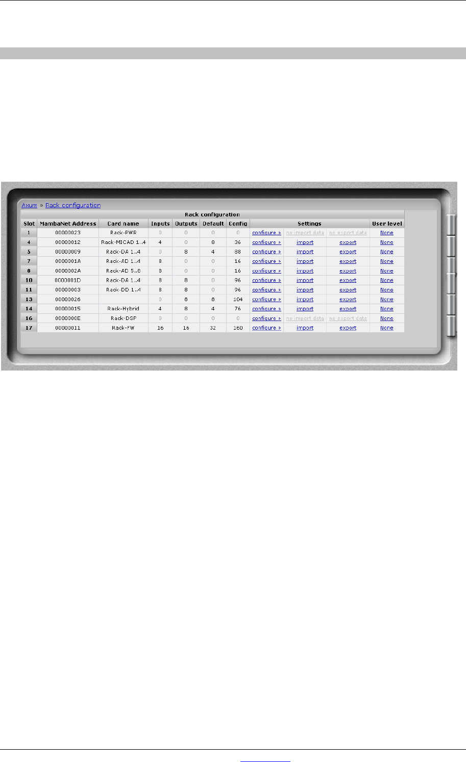
6.1.15 Rack configuration
You can see an overview of the cards in the rack on this page. You can find information like the slot
number, MambaNet address, card name, number of inputs and outputs.
The link Configure will go to a page for connecting objects of the card to Axum engine’s functions.
You can consider this as the remote control configuration. For example you can connect:
• Start/stop functionality to remote outputs
• Source gain functionality to MIC gain
• Speaker level to CRM output level
• etc. etc.
Figure 26: Rack configuration
• Slot
Slot number where the I/O card is located.
• MambaNet Address
Show information on the internal used MambaNet addresses
• Node name
Logical name of the node
• Inputs
Number of mono input channels
• Outputs
Number of mono output channels
• Default
Number of objects that have a default value set.
• Config
Number of objects that are configured to an engine function.
• Import/Export
Once you have configured the defaults and used engine functions you can export and import
these settings. With export the current configuration is stored in the database, where you have
to give a logical name (e.g. Module 5-8). With import you can restore a configuration to the
same or a different node (of the same type). When you import Module 5-8 with an offset of -4
the configuration will be as you expect Module 1-4.