
User manual


Table Of Contents
- 1 Table of contents1 T
- 2 Package Contents
- 3 Introduction
- 4 System overview
- 5 Control Surfaces
- 6 AXUM Engine
- 6.1 Console 1-4 configuration
- 6.1.1 IP/Clock configuration
- 6.1.2 Global configuration
- 6.1.3 Mix buss configuration
- 6.1.4 Monitor buss configuration
- 6.1.5 Source configuration
- 6.1.6 Extern source configuration
- 6.1.7 Destination configuration
- 6.1.8 Talkback configuration
- 6.1.9 Processing presets
- 6.1.10 Module assignment
- 6.1.11 Module configuration
- 6.1.11.1 Module configuration page
- 6.1.11.2 Module preset 1A/1B, 2A/2B, 3A/3B, 4A/4B
- 6.1.11.3 Processing
- These are the programmed processing defaults for the modules. Depending on the startup settings these processing defaults will be used at startup (programmed defaults in global configuration).The field ‘Use at source select’ determines if the default module processing in the source configuration is used when a source is assigned via the module source select functionality and no processing preset is assigned in the ‘source configuration’.
- The following state/value processing sections are available:
- 6.1.11.4 Routing
- 6.1.11.5 Set module 1 to programmed startup state
- 6.1.12 Mix/monitor buss presets
- 6.1.13 Console presets
- 6.1.14 Surface configuration
- 6.1.15 Rack configuration
- 6.1.16 Source pools
- 6.1.17 Preset pools
- 6.1.18 Users
- 6.2 System configuration
- 6.1 Console 1-4 configuration
- 7 Surface(s) website
- 8 Block diagrams – Must be created
- 9 I/O Rack description
- 10 Available I/O rack cards
- 11 Patch panels
- 12 Specifications AXUM digital audio system
- 13 List Of Figures
- 14 List Of Tables
- 15 Declaration Of Conformity
- 16 Product Safety
- 17 Disclaimer
- 18 Appendix A - Network design for AXUM
- 19 Appendix B – Surface service
- 20 Appendix C – Engine functions
A·X·U·M User Manual Version 2.5 - 2011-01-28
AXUM from D&R - Phone: +31 294 418014 - E-Mail: info@d-r.nl - 42 -
same or a different node (of the same type). When you import Module 5-8 with an offset of -4
the configuration will be as you expect Module 1-4.
• User level
Here you can define to which console the module belongs in terms of user level. The user
level depends on the user logged on to the AXUM system. If ‘None’ is selected this node will
always have full access.
• Configure
When you follow the link configure, you are able to setup the functionality for the different
objects on the node. The sensor and actuator data types determine which function is able to
connect to the object. For a complete list of the functions, you can go to chapter 20 Appendix
C – Engine functions.
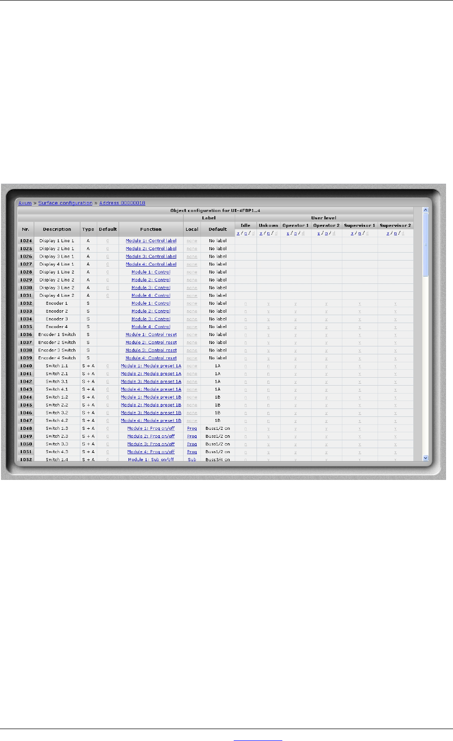
Figure 25: Node object configuration (to Axum functions)
• Default
The gray value is the startup default, this may be changed by assigning a custom value.
When you submit an empty box the object returns to the startup default value.
• Function
Here you may select which engine function is connected to the object
• Label
Here you may change the label, which is a shortcut for the selected function, if none is given
the default function label will be used (the label will appear in the remote configuration
software).
• User level
Per user level you can overwrite the default level per function. If y is selected the function will
be available in the selected user level. If n is selected the function won´t be available. if the y/n
value is shown light gray, the function default user level is used.
In the column headers you may toggle the user level for all objects in the node.